
Method and system for thermally treating dispersible raw materials

A raw, decentralized technology for climate sustainability, lighting and heating equipment, furnaces, etc., that solves problems such as high complexity of installation equipment, eliminates high complexity, avoids temperature peaks, and promotes temperature regulation

Active Publication Date: 2020-03-17
THYSSENKRUPP IND SOLUTIONS AG +1
View PDF5 Cites 0 Cited by
  • Summary
  • Abstract
  • Description
  • Claims
  • Application Information

AI Technical Summary

Problems solved by technology

While this approach has the advantage of a corresponding reduction in the complexity of the installations associated with the tertiary air lines, the corresponding high complexity of the installed equipment due to the extremely high temperatures must be taken into account

Method used


Image

  • Method and system for thermally treating dispersible raw materials
  • Method and system for thermally treating dispersible raw materials
  • Method and system for thermally treating dispersible raw materials

Examples


Embodiment Construction

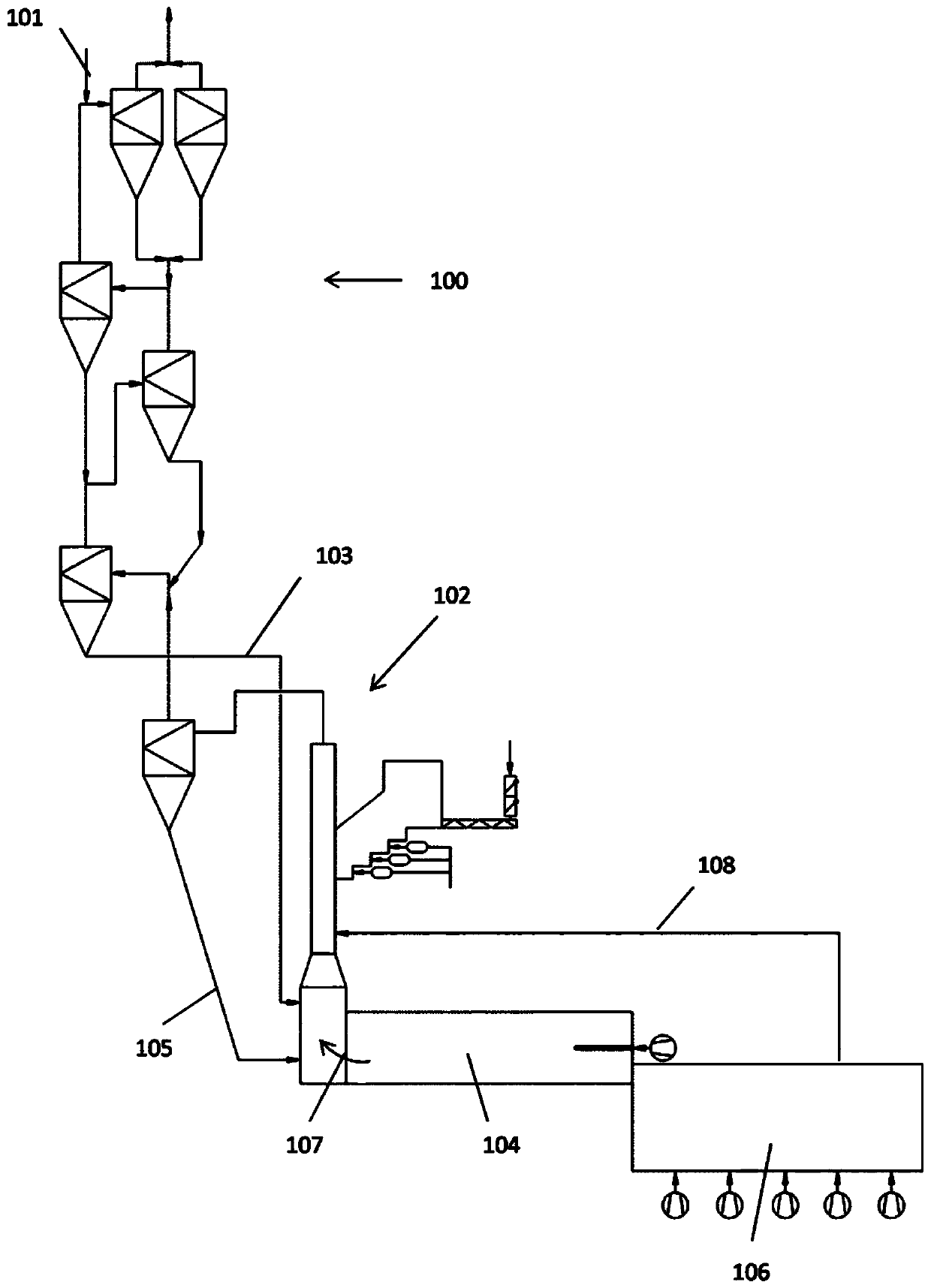
[0027] figure 1 Shown is a system for producing cement clinker with a multi-stage preheater 100 for preheating cement raw meal 101, a calciner 102 for precalcining preheated cement raw meal 103, a calciner 102 for calcining A furnace 104 for firing pre-calcined cement raw meal 105 to form cement clinker, and a cooler 106 for cooling the cement clinker. The hot gases 107 produced in the furnace 104 first flood the calciner 102 and then the preheater 100 . Furthermore, cooler off-gas 108 produced in cooler 106 is used as combustion air in calciner 102 .

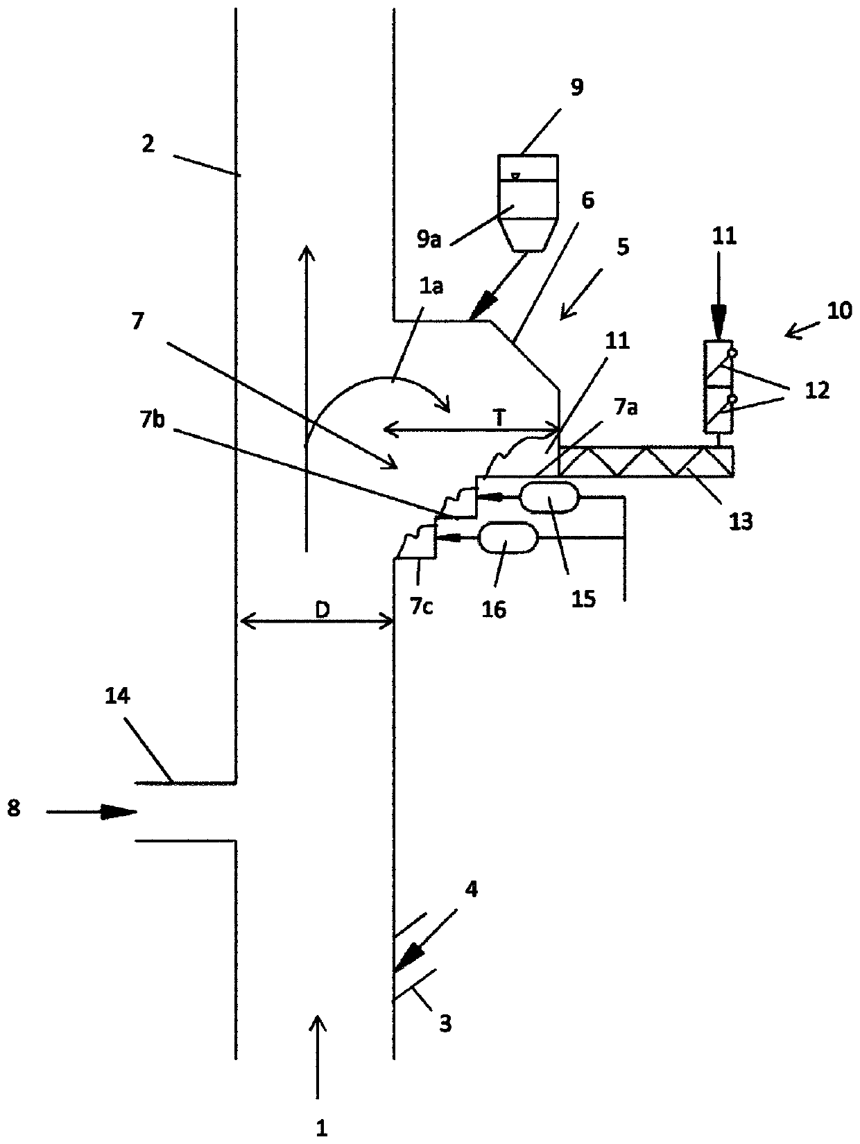
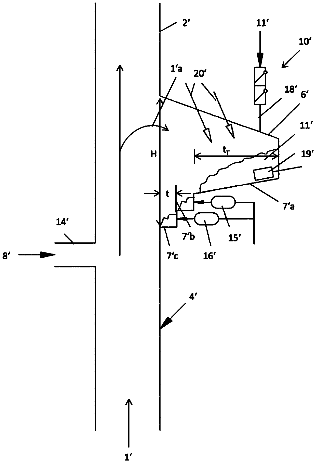
[0028] pass Figures 2 to 4 Various exemplary embodiments of the configuration of the calciner are shown. However, these exemplary embodiments may also relate to other systems for thermal treatment or chemical reactions of dispersible raw materials (eg ore reduction) and are therefore not limited to calciners.

[0029] figure 2 The system for thermally treating dispersible raw materials shown in has a standpipe 2 filled w...


PUM


Abstract

The invention relates to a method for thermally treating dispersible raw materials, wherein the raw material is introduced into a standpipe filled with hot gas, in which the raw material is thermally treated by the hot gas. Furthermore, supplying at least one fuel to the standpipe, wherein the fuel initially rests in a fuel conditioning zone on at least one support surface, where said fuel comes into contact with a portion of the hot gas mixed with raw materials, thus drying and / or At least partially degassed and / or at least partially reacted for subsequent transfer to a standpipe.

Description

technical field [0001] The present invention relates to a method and a system for thermally treating dispersible raw materials, wherein the raw material is introduced into a standpipe filled with one or more hot gases and heat-treated in the standpipes by one or more hot gases, respectively. Background technique [0002] Such heat treatment is performed, for example, in the calcination of cement raw materials in the production of cement clinker. The required thermal energy is provided by fuel burned in a separate combustion chamber, which is connected, for example, to a standpipe (DE 10 2004 045510 A1). A similar concept is known from DE 195 35 312 A1, which discloses a reactor connected to the discharge line, which reactor generates combustible gases from waste materials, in particular used tyres. The reactor in this document is constructed in the form of a gasification reactor and is connected by a tertiary air line to the cooler of the cement clinker system, so that at l...

Claims


Application Information

Patent Timeline
Patent Type & Authority Patents(China)
IPC IPC(8): C04B7/44F27B7/20F27B7/32F27B7/34
CPCC04B7/4446F23G2206/201F27B7/20F27B7/2033F27B7/32F27B7/34Y02E20/30
Inventor D·克莱格拉夫S·弗里耶H·布林克舒尔特
Owner THYSSENKRUPP IND SOLUTIONS AG
Learn More