
Oil discharging structure for bearing

An oil-draining structure and bearing technology, applied in the direction of bearings, shafts and bearings, bearing components, etc., can solve the problems of reduced oil-draining performance and retention of lubricating oil.

Active Publication Date: 2017-05-10
KAWASAKI HEAVY IND LTD
View PDF14 Cites 1 Cited by
  • Summary
  • Abstract
  • Description
  • Claims
  • Application Information

AI Technical Summary

Problems solved by technology

Therefore, in the above-mentioned oil discharge structure, the lubricating oil forming the swirling flow tends to stagnate in the middle of the oil discharge path, and the oil discharge performance decreases.

Method used


Image

  • Oil discharging structure for bearing
  • Oil discharging structure for bearing
  • Oil discharging structure for bearing

Examples


Embodiment Construction

[0030] Hereinafter, embodiments of the present invention will be described with reference to the drawings, but the present invention is not limited to the embodiments.

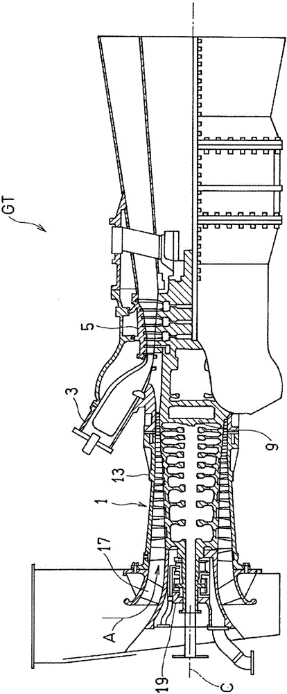
[0031] figure 1 A schematic structure of a gas turbine engine (hereinafter simply referred to as a gas turbine) GT to which an oil discharge structure of a bearing according to an embodiment of the present invention is applied is shown. The gas turbine GT compresses the air A introduced by the compressor 1, guides it to the combustor 3, injects fuel into the combustor 3 to combust it together with the air A, and drives the turbine 5 with the high-temperature and high-pressure combustion gas obtained through the combustion. The turbine 5 is connected to the compressor 1 via a rotor 9 as a rotating shaft, and the compressor 1 is driven by the turbine 5 . In the following description, the compressor 1 side in the axial center C direction of the gas turbine GT may be referred to as a "front side", and the turbine...


PUM


Abstract

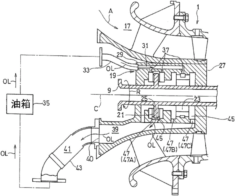
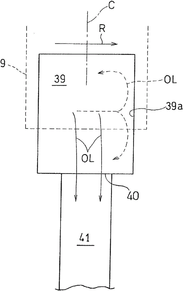
An oil discharge structure for a bearing, the oil discharge structure being provided with: at least one bearing (21) for rotatably supporting a rotating shaft (9); a cylindrical bearing housing (27) provided to the radially outer side of the bearing, the bearing housing (27) accommodating the bearing; an oil recovery chamber (39) provided radially outside of the bearing housing, the oil recovery chamber (39) recovering lubricating oil supplied to the bearing; and an oil discharge passage (47) passing radially through a peripheral wall (29) of the bearing housing (27) and discharging lubricating oil from the bearing to the oil recovery chamber (39), wherein a dividing wall (51) that circumferentially divides the oil discharge passage is provided to the oil discharge passage (47).

Description

[0001] related application [0002] This application claims priority from Japanese Patent Application No. 2014-116010 filed on Jun. 4, 2014, the entire content of which is incorporated by reference, as a part of this application. technical field [0003] The present invention relates to an oil discharge structure for a bearing that rotatably supports a rotary shaft. Background technique [0004] In a device having a rotating shaft rotating at high speed, such as a gas turbine engine, lubricating oil supplied to bearings supporting the rotating shaft is generally discharged to the outside of the device through an oil discharge pipe connected to the outer peripheral portion of a bearing housing housing the bearing. [0005] On the other hand, the lubricating oil in the bearing housing is affected by the rotation of the rotating shaft, and swirls at a high speed around the bearing, especially on the outer peripheral side. Therefore, in the above-mentioned oil discharge structu...

Claims


Application Information

Patent Timeline
Patent Type & Authority Applications(China)
IPC IPC(8): F16C33/10F01D25/16F01D25/18F02C7/06F16C17/04F16N31/00
CPCF01D25/18F02C7/06F16N31/00F16C17/04F01D25/16F05D2260/98F05D2250/14F16C17/02F16C17/26F16C33/106F16C33/1045F16C2360/44F16N2210/02F16N2210/14F01M11/04F16C33/10F02C3/04F02C7/04F05D2220/32F05D2240/52F05D2240/60
Inventor 筱原善哉有泽秀则山下诚二田中胜也吉田毅
Owner KAWASAKI HEAVY IND LTD
Learn More