Methods of detecting flow line deposits using gamma ray densitometry

A technology of flow pipelines, gamma rays, applied in the use of wave/particle radiation for material analysis, measuring devices, using wave/particle radiation, etc.

Inactive Publication Date: 2017-05-10
SHELL INT RES MAATSCHAPPIJ BV
View PDF4 Cites 0 Cited by
  • Summary
  • Abstract
  • Description
  • Claims
  • Application Information

AI Technical Summary

Problems solved by technology

It is not practical to cover every foot of

Method used


Image

  • Methods of detecting flow line deposits using gamma ray densitometry
  • Methods of detecting flow line deposits using gamma ray densitometry
  • Methods of detecting flow line deposits using gamma ray densitometry

Examples


example 1

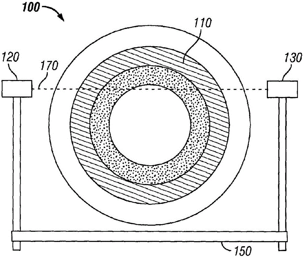
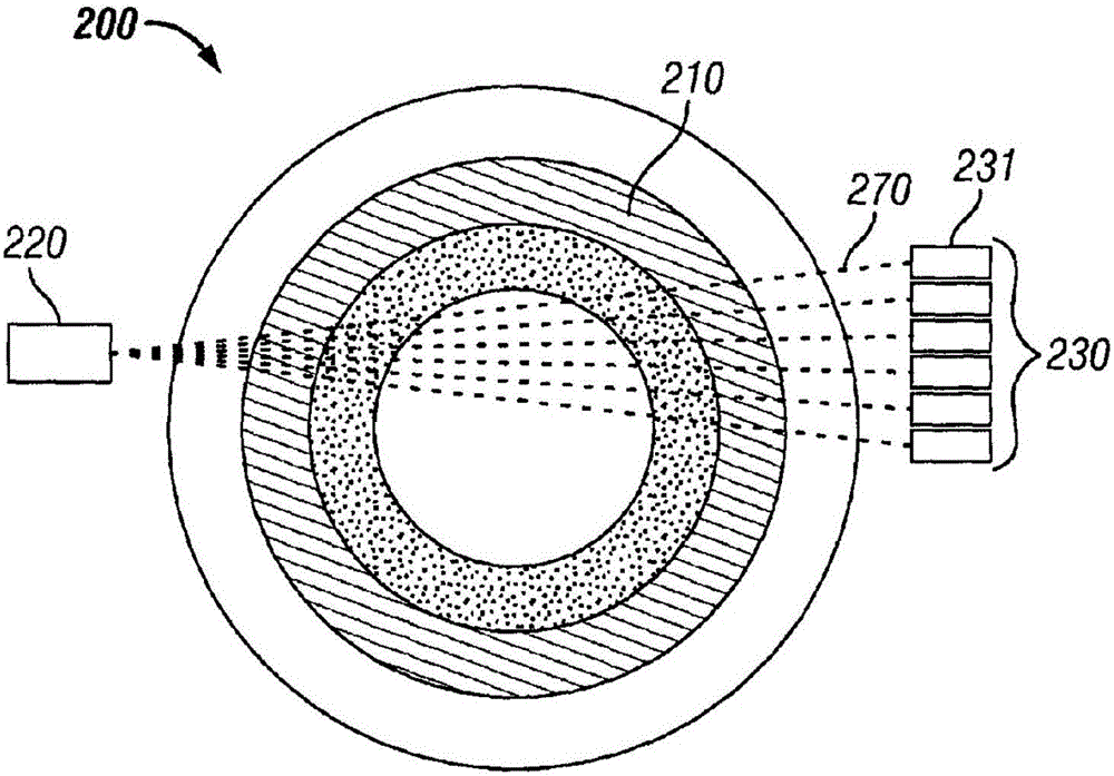
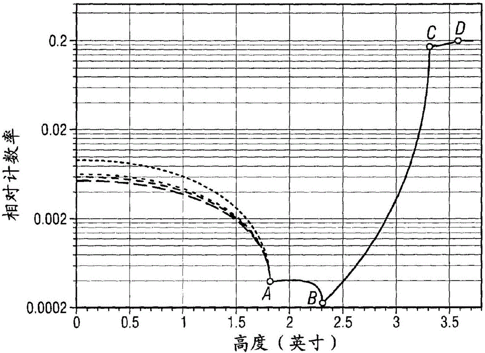
[0056] The first pipe had an inner diameter of 4.6 inches, an outer diameter of 6.6 inches, and was coated with a wax deposit of 0.3 inches. Fouling deposits were used to prepare a second pipe having an inner diameter of 4.6 inches, an outer diameter of 6.6 inches, and a coating of 0.3 inches. A mixture of oil and natural gas flows through the first pipeline and the second pipeline. Densitometers including sources and detectors were placed on either side of each tube and photon counts were measured at different heights along the axis of each tube. The relative counts of photons measured for each pipeline are plotted on the graph. Figure 6 Show the results of this graph. Analyzing the graph, it was determined that the deposit thickness on each pipe was 0.5 inches by locating points of intersection and minima.

example 2

[0058] In addition to the first and second pipes in Example 1, a third pipe was prepared having an inner diameter of 4.6 inches, an outer diameter of 6.6 inches, and a coating of 0.3 inches. The same mixture of oil and gas as the first and second conduits flows through the third conduit. Densitometers including sources and detectors were placed on either side of the third tube and photon counts were measured at different heights along the axis of each tube. The relative counts of photons measured for both the first and second conduits are divided by the relative counts of photons measured for the third conduit to obtain corrected decay counts, and will be corrected for each of the first and second conduits The decay counts for are plotted on the graph. Figure 7 Plot the results of this chart. Analysis of the graph, by locating local minima and junctions, determined that the deposit thickness on each pipe was 0.5 inches.

example 3

[0060] Use the following equation to calculate the thickness of the sediment measured for each chord of the first and second conduits:

[0061]

[0062] For both the first and second pipelines, one obtains μ Water , μ insulation , μ wall , μ stream and μ deposit value. Compute l at each chord using the following equation Water value, l insulation value and l wall value:

[0063] l=2[(R 1 )Sin(a cos(h / R 1 )-(R 2 )Sin(a cos(h / R 2 )]

[0064] Once each l is calculated for each chord length deposit value, to determine the largest l for the first and second pipelines deposit The value is 0.5 inches.


PUM


Abstract

A method of measuring a flow line deposit comprising: providing a pipe comprising the flow line deposit; measuring unattenuated photon counts across the pipe; and analyzing the measured unattenuated photon counts to determine the thickness of the flow line deposit and associated systems.

Description

[0001] Cross References to Related Applications [0002] This application claims the benefit of U.S. Provisional Application No. 62 / 027,574, filed July 22, 2014, which is incorporated herein by reference. technical field [0003] The present disclosure generally relates to methods for detecting flow line deposits using gamma ray densitometry. More specifically, in certain embodiments, the present disclosure relates to methods and associated systems for measuring flowline deposit thickness using non-invasive gamma-ray densitometry. Background technique [0004] In the oil and gas industry, deposits of material from produced fluids in flow lines are a frequent occurrence. If left unattended, these deposits build up over time and reduce the effective cross-sectional area available for flow, thereby increasing pressure drop or reducing hydrocarbon flow. In extreme cases, deposits can build up to fill the lumen, causing a complete blockage of the flow line, thereby affecting th...

Claims


Application Information

Patent Timeline
IPC IPC(8): G01B15/02
CPCG01B15/02G01N23/083G01N2223/101G01N2223/633G01B15/025
Inventor R·瓦尔玛G·J·哈顿K·拉马纳坦
Owner SHELL INT RES MAATSCHAPPIJ BV
Why Eureka
Try Eureka