Check patentability & draft patents in minutes with Patsnap Eureka AI!

Controller and method for minimizing scale factor errors of a rotation rate sensor

A technology of rotation rate and control device, which is applied in the direction of measuring device, gyroscope/steering sensing equipment, instrument, etc., and can solve the problems affecting the measurement accuracy of rotation rate sensor

Active Publication Date: 2017-05-10
NORSROP GRUMAN LITEF GMBKH
View PDF5 Cites 2 Cited by
  • Summary
  • Abstract
  • Description
  • Claims
  • Application Information

AI Technical Summary

Problems solved by technology

Therefore, changes in the reference voltage based on aging directly affect the scale factor and thus the measurement accuracy of the rotation rate sensor
In the worst case, i.e., when the aging of the reference voltage causes aging-dependent errors to accumulate, the error due to changes in the reference voltage can be as high as the fourth power relationship

Method used


Image

  • Controller and method for minimizing scale factor errors of a rotation rate sensor
  • Controller and method for minimizing scale factor errors of a rotation rate sensor
  • Controller and method for minimizing scale factor errors of a rotation rate sensor

Examples


Embodiment Construction

[0040] In the figures, parts or groups of parts corresponding to each other are marked with the same reference numerals.

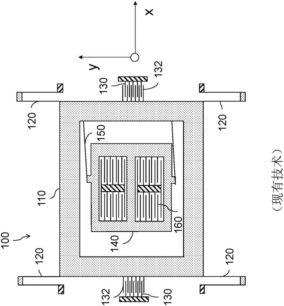
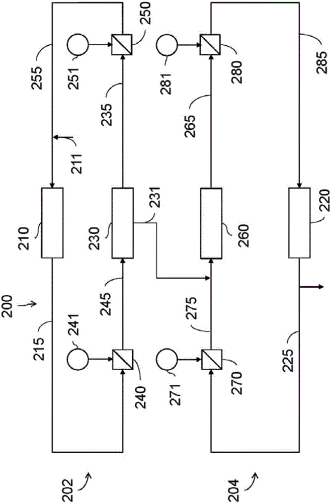
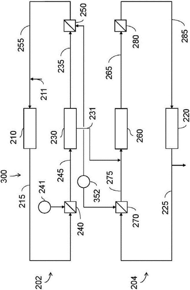
[0041] figure 2 A schematic block diagram of a control device 200 for controlling a rotation rate sensor is shown. The rotation rate sensor can refer to the reference figure 1 the sensor. The rotation rate sensor may be, for example, a microelectromechanical sensor (MEMS).

[0042] The control device 200 has a first control loop 202 and a second control loop 204 . The first control loop 202 has a first control unit 210 for controlling an excitation unit 230 . The first control unit 210 can control the MEMS through the excitation unit 230 or according to figure 1 The rotation rate sensor is along a first direction, for example along figure 1 Vibration in the x-direction. In addition, the excitation unit 230 can be as figure 1 As shown, there are one or more excitation electrodes 130 and electrodes 132 .

[0043] Furthermore, the first control unit...


PUM


Abstract

The invention relates to a controller (200) for controlling a rotation rate sensor, having a first control circuit (202) and a second control circuit (204). The first control circuit has a first control unit (210) for controlling an oscillation of the rotation rate sensor along a first direction, a first digital-to-analog converter (240) for converting a first digital control signal (215) output by the first control unit (210) into a first analog signal (245) with which the oscillation of the rotation rate sensor along the first direction is controlled, and a first analog-to-digital converter (250) for converting a first analog measurement signal (235) which describes the oscillation of the rotation rate sensor along the first direction into a first digital read-out signal (255) which is supplied to the first control unit (210). The second control circuit (204) has a second control unit (220) for controlling an oscillation of the rotation rate sensor along a second direction which is different from the first direction and a second digital-to-analog converter (270) for converting a second digital control signal (225) output by the second control unit into a second analog signal (275) with which the oscillation of the rotation rate sensor along the second direction is controlled. During the conversion process, the first digital-to-analog converter (240), the second digital-to-analog converter (270), and the first analog-to-digital converter (250) each operates using a reference voltage (241, 251, 271), and at least two of the reference voltages (241, 251, 271) of the first digital-to-analog converter (240), the second digital-to-analog converter (270), and the first analog-to-digital converter (250) are dependent on each other.

Description

technical field [0001] The invention relates to a device for minimizing a reference voltage-induced scale factor error of a rotation rate sensor, and a method for minimizing the scale factor error. Background technique [0002] Control loops are used in many sensors of today's technology to control and regulate the various components of the sensor to specific values. In this case, it is usually necessary to convert the digital control variable into an analog signal by means of which the component to be controlled can be directly controlled. Likewise, it may be necessary to convert an analog measurement signal representing the response of a component based on an analog control signal to a digital signal that can be compared to the control variable. For this purpose, digital-to-analog converters and / or analog-to-digital converters are used in the sensors to convert digital signals into analog signals and vice versa. [0003] Digital-to-analog converters and analog-to-digital...

Claims


Application Information

Patent Timeline
Patent Type & Authority Applications(China)
IPC IPC(8): G01C19/5726
CPCG01C19/5726G01C19/5762
Inventor 拉尔夫·理查德·欧姆伯杰史蒂芬·齐默尔曼
Owner NORSROP GRUMAN LITEF GMBKH
Features
  • R&D
  • Intellectual Property
  • Life Sciences
  • Materials
  • Tech Scout
  • Unparalleled Data Quality
  • Higher Quality Content
  • 60% Fewer Hallucinations
Learn More