Orthopedic nursing traction frame

A technology of orthopedics and support columns, applied in fractures, medical sciences, etc., can solve the problems of inconvenient adjustment and control of traction strength, adverse recovery of patients, and achieve the effect of avoiding the suspension of legs

Inactive Publication Date: 2017-05-17
LUOYANG ORTHOPEDIC TRAUMATOLOGICAL HOSPITAL
View PDF5 Cites 22 Cited by
  • Summary
  • Abstract
  • Description
  • Claims
  • Application Information

AI Technical Summary

Problems solved by technology

[0004] With regard to the above-mentioned prior art, the purpose of the present invention is to overcome the inconvenient adjustment and control of the traction force of the orthopedic traction bracket in the prior art, which is not conducive to the recovery of the patient's condition, and may cause the patient more painful problems during the treatment process, thus Provide a simple structure, easy to use, can clearly grasp the strength of the traction, and can adjust the orthopedic nursing traction bracket

Method used


Image

  • Orthopedic nursing traction frame
  • Orthopedic nursing traction frame
  • Orthopedic nursing traction frame

Examples


Embodiment Construction

[0037] Specific embodiments of the present invention will be described in detail below in conjunction with the accompanying drawings. It should be understood that the specific embodiments described here are only used to illustrate and explain the present invention, and are not intended to limit the present invention.

[0038] In the present invention, in the absence of a contrary description, the orientation words such as "upper, lower" and the like included in the term only represent the orientation of the term in the normal use state, or the common name understood by those skilled in the art, and should not be viewed as a limitation of this term.

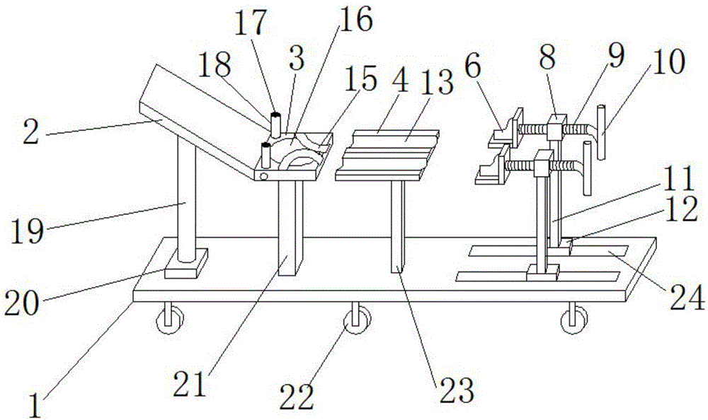
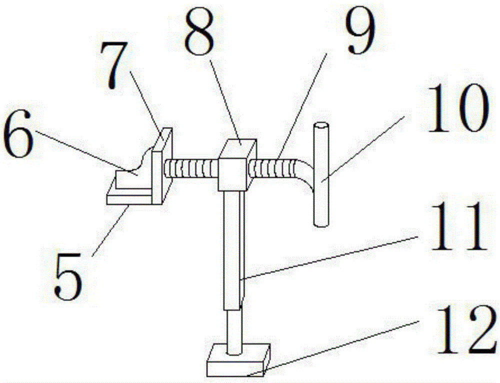
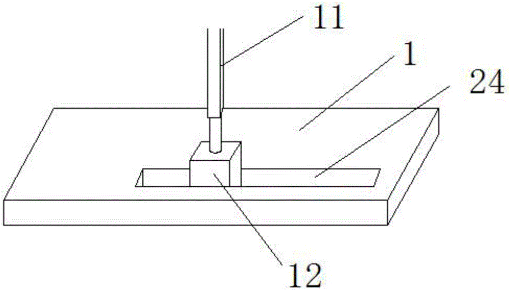
[0039] Such as figure 1 , figure 2 , image 3 , Figure 4 , Figure 5 , Figure 6 and Figure 7 As shown, the present invention provides an orthopedic nursing traction bracket, which includes: a base 1, a first support column 19, a backboard 2, a seat board 3, a leg brace 4, and a foot stretching mechanism and the first h...


PUM


Abstract

The invention discloses an orthopedic nursing traction frame which comprises a base, a first support column, a back plate, a seat plate, a leg support plate, two leg stretching mechanisms, a first hydraulic pump, a second support column and a third support column. The first hydraulic pump, the second support column and the third support column are respectively arranged on the base, the first support column is vertically arranged, the upper end of the first support column is hinged to the lower surface of the back plate, the seat plate is horizontally arranged at the upper end of the second support column, a side of the back plate is hinged to a side of the seat plate, the leg support plate is horizontally arranged at the upper end of the third support column, two strip-shaped leg accommodating grooves are formed in the upper surface of the leg support plate, the two leg stretching mechanisms which are matched with the leg support plate are further respectively arranged on the base, tension sensors are arranged between foot sleeves and fixing plates on the two leg stretching mechanisms, and displays which are electrically connected with the tension sensors are arranged on the surfaces, which face the seat plate, of the fixing plates. The orthopedic nursing traction frame has the advantage that the problem of inconvenience in adjusting and controlling traction force of existing orthopedic traction frames in the prior art can be solved by the aid of the orthopedic nursing traction frame.

Description

technical field [0001] The invention relates to the field of medical devices, in particular to orthopedic nursing traction brackets. Background technique [0002] Traction is a commonly used treatment method in orthopedics, and orthopedic traction bracket is a novel device that adopts mechanical transmission to perform traction. It is widely used in various acute and chronic injuries by combining the characteristics of human physiology and mechanical physics. Intervertebral disc herniation, lumbago and leg pain, radioactive numbness of legs and feet, muscle atrophy of legs and feet caused by walking weakness, and traumatic cervical spine fractures, dislocations, dislocations, etc. It can also be applied to clinical symptoms such as cervical dizziness, headache, tinnitus, and abnormal blood pressure. However, the orthopedic traction brackets in the prior art are inconvenient to adjust and grasp the traction strength, which is not conducive to the recovery of the patient's con...

Claims


Application Information

Patent Timeline
Patent Type & Authority Applications(China)
IPC IPC(8): A61F5/042
CPCA61F5/042
Inventor 杨玉霞焦瑞娜田静娟倘艳锋杨桦
Owner LUOYANG ORTHOPEDIC TRAUMATOLOGICAL HOSPITAL
Why Eureka
Try Eureka