Automatic pipe-cleaning water-cutting oil-returning method and system for multiple storage tanks

An automatic cleaning and storage tank technology, applied in separation methods, chemical instruments and methods, transportation and packaging, etc., can solve the problems of medium loss environment, pollution, disturbance of oil-water interface, etc., to prevent oily medium from cutting water and avoid environmental pollution. Pollution, the effect of efficient water cutting

Active Publication Date: 2017-05-17
凯泰(滁州)流体控制有限公司
View PDF4 Cites 0 Cited by
  • Summary
  • Abstract
  • Description
  • Claims
  • Application Information

AI Technical Summary

Problems solved by technology

[0002] The medium storage tanks in the petrochemical industry are mostly multi-tank integrated configurations due to the need for economies of scale. In order to prevent the oil-water interface from being disturbed during drainage, most of them are equipped with siphon drainage pipelines, that is, the inner ports of the drainage pipelines in the storage tanks face downward. During the water cutting process, the medium entering the siphon drainage pipeline and the water cutter cannot return to the oil by itself through the storage tank drainage pipeline due to the gravity difference of waterlogging; and although some drainage pipelines are straight drainage pipes, due to the viscosity coefficient of the oily medium and the drainage pipeline For reasons such as fineness, it is impossible to return the oil through the drainage pipeline by relying on the gravity difference of oil and water.
Therefore, when the water is cut, the water from the storage tank must pass through the drainage pipeline and the medium in the water cutter. In this way, when the water passes through the drainage pipeline and the medium in the water cutter, the medium must be entrained, resulting in unnecessary medium loss and Environmental pollution after the medium is lost to the water body

Method used


Image

  • Automatic pipe-cleaning water-cutting oil-returning method and system for multiple storage tanks
  • Automatic pipe-cleaning water-cutting oil-returning method and system for multiple storage tanks
  • Automatic pipe-cleaning water-cutting oil-returning method and system for multiple storage tanks

Examples


Embodiment 1

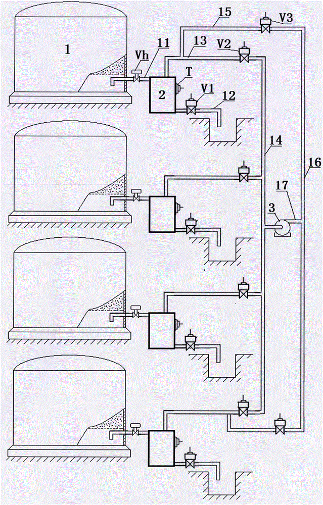
[0022] Embodiment one, such as figure 1 As shown, the multi-storage tank automatic pigging, water cutting and oil return method of the present invention is that the respective siphon drain pipes 11 (or straight discharge drain pipes) of multiple storage tanks 4 storing similar media are respectively equipped with manual valves Vh, and are connected to each other respectively. The upper part of the water cutter 2 equipped with the medium detection head T; the lower two parts of the water cutter are connected to the water cutting pipe 12 equipped with the water cutting control valve V1, and the top of the water cutter 2 is respectively connected through the front oil return branch pipe 13 equipped with the front oil return control valve V2 The front oil return collecting pipe 14, the front oil return branch pipes 13 of any two water cutters 2 are respectively connected to the rear oil return branch pipe 15 of the rear oil return control valve V3 upstream of the oil return control...

Embodiment 2

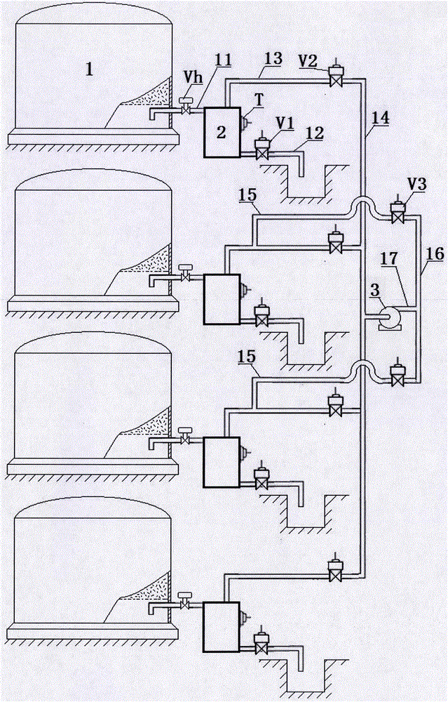
[0035] Embodiment two, such as figure 2 As shown, the difference between the multi-storage tank automatic pigging method and system for automatic pigging, cutting water and oil return of the present invention and Embodiment 1 is that the storage tanks 4 are the 1st-N storage tanks 4 arranged in sequence from front to back, and are respectively separated by siphon Type drain pipe 11, water cutter 2 and front oil return branch pipe 13 are connected to the front oil return collecting pipe 14 from front to back; the front oil return branch pipe 13 of the middle two storage tanks 4 is connected to the rear oil return branch pipe 15, and the middle two storage tanks 4 extend The front oil return collection pipe section between the two front oil return branch pipes 13 in the middle is connected to the rear oil return collection pipe 16 through the front and back oil return pipes 17 connected in series of the oil return pump 3 .

Embodiment 3

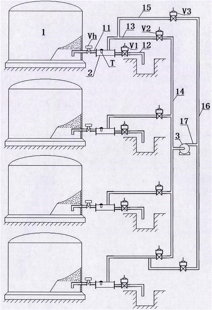
[0036] Embodiment three, such as image 3 As shown, the difference between the multi-storage tank automatic pigging, water cutting and oil return method and system of the present invention and the first embodiment is that the medium detection head T is configured to be inserted and installed downward from the upper middle of the thick horizontal pipe water cutter 2 body. The resistive or dielectric constant type medium detection probe T.

[0037] After adopting the above technical solution, the multi-storage tank automatic pigging method and system for water cutting and oil return of the present invention have the advantages of not only preventing oily medium from cutting water, but also timely concentrated and efficient water cutting and smooth flow of water cutting and oil return pipelines.


PUM


Abstract

The invention relates to an automatic pipe-cleaning water-cutting oil-returning method and system for multiple storage tanks, in order to solve the problem of medium residue and carrying in a draining pipeline and a water cutter. Direct discharging type or siphoning type draining pipes of a plurality of storage tanks for storing same media are respectively equipped with manual valves and are respectively connected with the water cutters with medium detectors; the water cutters are connected with water-cutting pipes equipped with water-cutting control valves; the tops of the water cutters are jointly connected with a front return oil converging pipe through front return oil branches equipped with front return oil control valves; the front return oil branches of any two water cutters at the upstream sides of the return oil control valves thereof are respectively connected with rear return oil branches equipped with rear return oil control valves; two rear return oil branches are jointly connected with a rear return oil converging pipe; a return oil pump is connected between the front return oil converging pipe and the rear return oil converging pipe; and the medium detectors, the control valves and the return oil pump are electrically connected with an automatic controller. The invention has the advantages that the oily medium carried by the cut water is eliminated, the environmental pollution is avoided, water can be timely, centrally and efficiently cut, and the smoothness of the water-cutting oil return pipeline is benefited.

Description

technical field [0001] The invention relates to a water cutting method for storage tanks, in particular to an automatic pigging method and system for water cutting and oil return of multi-storage tanks. Background technique [0002] The medium storage tanks in the petrochemical industry are mostly multi-tank integrated configurations due to the need for economies of scale. In order to prevent the oil-water interface from being disturbed during drainage, most of them are equipped with siphon drainage pipelines, that is, the inner ports of the drainage pipelines in the storage tanks face downward. During the water cutting process, the medium entering the siphon drainage pipeline and the water cutter cannot return to the oil by itself through the storage tank drainage pipeline due to the gravity difference of waterlogging; and although some drainage pipelines are straight drainage pipes, due to the viscosity coefficient of the oily medium and the drainage pipeline For reasons s...

Claims


Application Information

Patent Timeline
IPC IPC(8): B01D17/032B65D90/00
CPCB01D17/0214B65D90/00
Inventor 高翔
Owner 凯泰(滁州)流体控制有限公司
Why Eureka
Try Eureka