
Inertia removal device and weight grading scale

A technology for rejecting devices and sorting scales, which is applied in packaging, packaging protection, transportation and packaging, etc. It can solve the problems of large space occupation, long reset time, and large aerodynamic noise, and achieves small footprint and quiet sorting action , the effect of small aerodynamic noise

Inactive Publication Date: 2017-05-17
汤小牛 +1
View PDF8 Cites 10 Cited by
  • Summary
  • Abstract
  • Description
  • Claims
  • Application Information

AI Technical Summary

Problems solved by technology

If you fail consecutively, the blowing noise will be very disturbing, and sometimes cause the air pressure to drop so that it cannot work properly
[0005] Rotary lever: also known as a swing lever, pushing a heavy object or an object with a rough bottom surface will wear the belt; a high-speed action push rod or swing lever will damage the object being weighed; it is not suitable for ultra-thin objects, such as paper, mask, small Empty drug bag, easy to jam ultra-thin objects between the moving rod and the conveyor belt
[0006] Linear Actuator: The problem is the same as that of the rotary lever, and when continuous defective products pass, the actuator will repeatedly move back and forth, the noise will be very disturbing, and sometimes the air pressure will drop so that it cannot work properly
[0007] Vacuum nozzle: the control cost of sucking the moving object and then removing the object is high, the reset time is long, and the efficiency is low
[0008] Turning the belt conveyor or lifting belt conveyor with the outlet of the weighing unit as the axis: high manufacturing cost, large loads such as turning or lifting the belt conveyor cause large aerodynamic noise
[0009] In addition, the belt conveyor takes up a lot of space in the production line, it is very troublesome to disassemble, it is inconvenient to clean the belt, and the cost of waterproofing the drive motor and rotating bearing is high
In addition, nozzles, push rods, and swing rods can only perform two levels of sorting
[0010] It can be seen that the existing technologies of weight sorting scales all have complex structures, high manufacturing costs, difficult cleaning, high working noise, unsuitable for sorting and rejecting light and thin objects, poor reliability, easily damaged conveyor belts, and large space occupation. The problem

Method used


Image

  • Inertia removal device and weight grading scale
  • Inertia removal device and weight grading scale
  • Inertia removal device and weight grading scale

Examples


Embodiment 1

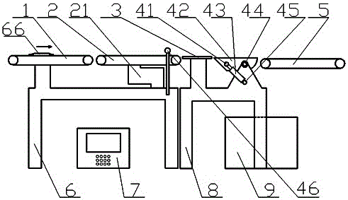
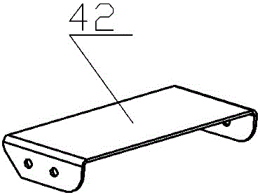
[0064] Embodiment 1: as figure 1 , 2 As shown, a weight sorting scale includes a frame 6 and a control cabinet 7, a feeding unit 1, and a weighing unit 2 arranged on the frame 6, and also includes at least one sorting mechanism, and each sorting mechanism corresponds to At least one receiving unit is set, and the sorting mechanism includes a support 8, a slide rail 42, the upper surface and the lower surface of the slide rail 42 are smooth slideways, the slide rail 42 is connected with the support 8 by a rotating shaft 44, and on the support 8 An overturn driving mechanism is provided to drive the slide rail 42 to rotate around the rotating shaft 44, and the feeding unit 1, the weighing unit 2, and the overturn driving mechanism are electrically connected to the control cabinet 7 respectively. The arrow points to the running direction of the object or the incoming material direction of the object.

[0065] A time-delay protection unit 3 is also arranged between the weighing ...

Embodiment 2

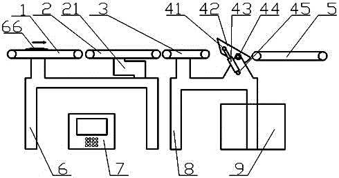
[0072] Embodiment 2: The similarities between this embodiment and Embodiment 1 will not be repeated, and the difference is: as Figure 4 As shown, a weight sorting scale, the delay protection unit 3 is a belt conveyor, and the belt conveyor is electrically connected to the control cabinet 7 .

Embodiment 3

[0073] Embodiment 3: The similarities between this embodiment and Embodiment 1 will not be repeated, and the difference is: as Figure 5As shown, a weight sorting scale has no delay protection unit 3 between the weighing unit 2 and the sorting mechanism; the feeding unit 1, the weighing unit 2, and the sorting mechanism are arranged in sequence, and stop at the slide rail 42 When the first static position, that is, the upper surface of the sliding rail 42 driven by the turning drive mechanism is in line with the incoming material direction of the object, and the object can slide smoothly from the upper surface of the sliding rail 42, the position of the object entrance on the upper surface of the sliding rail 42 is slightly lower. The position at the exit of the weighing unit 2 object.

[0074] This solution is suitable for rechecking that the weighing platform of the weighing unit 2 is very long or the output speed of the weighing result is very fast, so that the control cabi...


PUM


Abstract

The invention discloses an inertia removal device and a weight grading scale. The weight grading scale comprises a rack, a control cabinet, a feeding unit and a weighing unit, wherein the weighing unit is arranged on the rack. The weight grading scale further comprises one or more grading mechanisms. Each grading mechanism is correspondingly provided with one or more material receiving units. The weight grading scale is characterized in that each grading mechanism comprises a support and a slide rail; the upper surface and the lower surface of each slide rail serve as smooth slide ways; each slide rail is connected with the corresponding support through a rotating shaft; each support is further provided with an overturning driving mechanism which drives the corresponding slide rail to rotate around the rotating shaft; and the feeding unit, the weighing unit and the overturning driving mechanisms are electrically connected with the control cabinet. By controlling the overturning driving mechanisms, the slide rails can be located at different elevation angles, so that sorted objects are made to slide through the upper surfaces or the lower surfaces of the slide rails by means of motion inertia and are cast into the corresponding material receiving units, and therefore weight grading is achieved. The inertia removal device and the weight grading scale are simple in structure, low in manufacturing cost and easy to clear.

Description

technical field [0001] The invention relates to the field of automatic weighing and sorting, in particular to a weight detection scale and a weight grading scale. Background technique [0002] In the production and packaging process of food, medicine, daily chemical products, etc., it is necessary to check the weight of the product according to the production standards and measurement regulations, and select the overweight and ultra-light products, and some products need to be classified according to the weight of the product , these processes require a weighing check scale and a weight grading scale. [0003] When the weight detection scale and the weight grading scale are working, the objects are generally sent to the re-inspection scale one by one by the feeding belt conveyor; Most of the departments also use belt conveyors to transport objects, and some weight inspection departments use inclined slides to use the potential energy of objects to move objects; in order t...

Claims


Application Information

Patent Timeline
Patent Type & Authority Applications(China)
IPC IPC(8): B07C5/32B07C5/16B65B57/02
CPCB65B57/02B07C5/16B07C5/32
Inventor 汤小牛刘久明
Owner 汤小牛
Learn More