
Guiding and guarding clamping device and rolling machine

A technology of clamping device and guide, which is applied in the field of steel rolling machinery, can solve the problems that the guide device cannot be prevented from falling out, cannot be flexibly adjusted, and has poor load capacity, and achieves the effects of convenient maintenance and replacement, large load capacity, and improved efficiency

Active Publication Date: 2017-05-17
BEIJING JINGCHENG RUIXINCHANGCAI ENG TECH
View PDF6 Cites 3 Cited by
  • Summary
  • Abstract
  • Description
  • Claims
  • Application Information

AI Technical Summary

Problems solved by technology

[0006] In order to solve the technical problems that the guide device cannot prevent falling off, the load is poor, and it cannot be adjusted flexibly, the invention proposes a guide clamping device and a rolling mill, which can clamp the rolled piece, have high strength and rigidity, and have a large It has the functions of anti-shock, anti-rotation and anti-falling, and can be adjusted in real time online

Method used


Image

  • Guiding and guarding clamping device and rolling machine
  • Guiding and guarding clamping device and rolling machine
  • Guiding and guarding clamping device and rolling machine

Examples


Embodiment Construction

[0065] The above-mentioned technical features and advantages of the present invention will be clearly and completely described below in conjunction with the accompanying drawings. Obviously, the described embodiments are only part of the embodiments of the present invention, rather than all the embodiments.

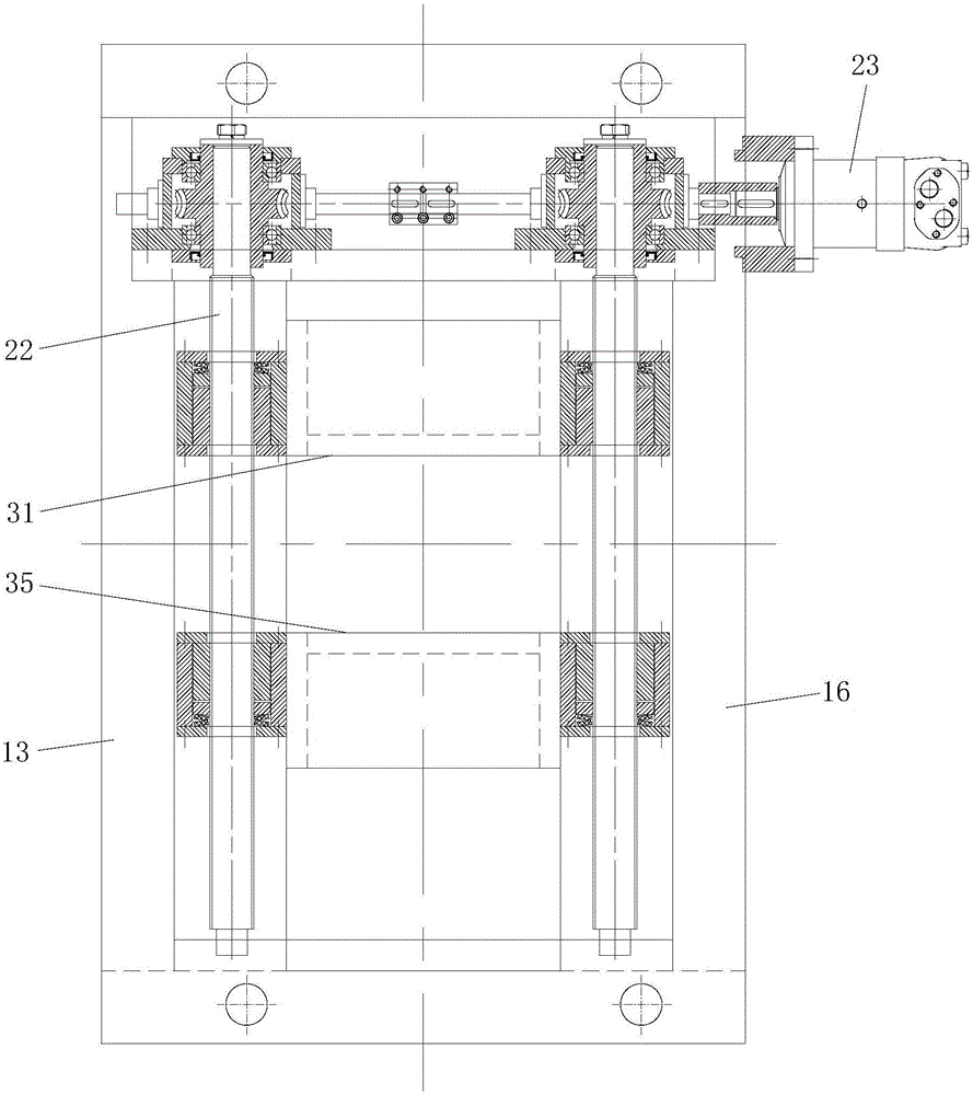
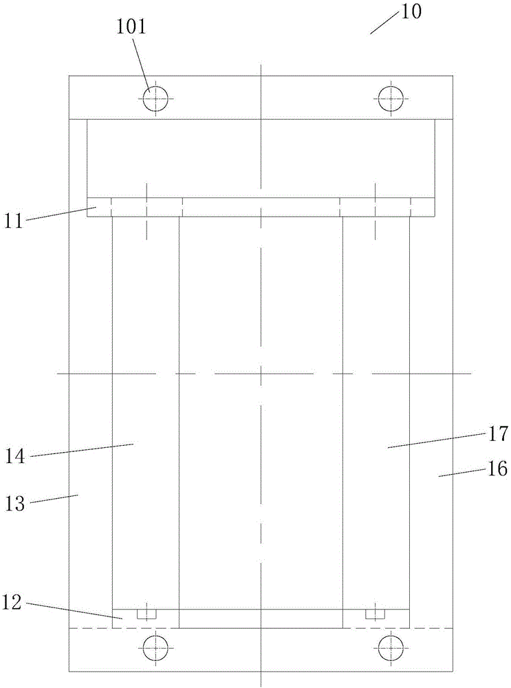
[0066] See figure 1 As shown, the present invention provides a guide and guard clamping device, which includes a frame 10, an adjustment mechanism and a guide and guard mechanism.

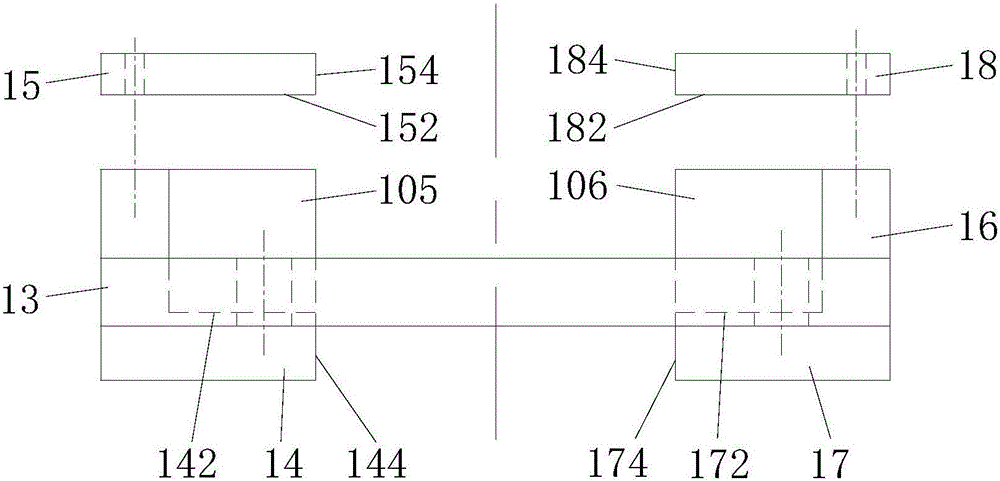
[0067] Please combine figure 2 , image 3 with Figure 4 As shown, the frame 10 includes an upper beam 11 and a lower beam 12 arranged oppositely, a first side wall 13 and a second side wall 16 arranged oppositely, a first front pressure plate 14 and a first rear pressure plate 15 arranged oppositely, and The second front pressure plate 17 and the second rear pressure plate 18. The first front pressure plate 14 and the first rear pressure plate 15 are both vertically connected to the first side wa...


PUM


Abstract

The invention provides a guiding and guarding clamping device and a rolling machine. The guiding and guarding clamping device comprises a framework, an adjusting mechanism comprising two screws and a guiding and guarding mechanism comprising an upper guiding and guarding box and a lower guiding and guarding box, wherein the framework comprises an upper cross beam and a lower cross beam which are opposite, a first side wall and a second side wall which are opposite, a first front pressing plate and a first rear pressing plate which are vertically connected to the first side wall, and a second front pressing plate and a second rear pressing plate which are vertically connected to the second side wall; a first sliding groove is defined by the first side wall, the first front pressing plate and the first rear pressing plate, and a second sliding groove is defined by the second side wall, the second front pressing plate and the second rear pressing plate; first and second external threads are separately arranged at the upper and lower parts of each screw; the two ends of the upper guiding and guarding box are separately arranged in a manner capable of sliding in the first sliding groove and the second sliding groove and are in surface contact with the first sliding groove and the second sliding groove; the two ends of the lower guiding and guarding box are separately arranged in a manner capable of sliding in the first sliding groove and the second sliding groove and are in surface contact with the first sliding groove and the second sliding groove; and the screws rotate and drive the upper and lower guiding and guarding boxes to slide in a face-to-face manner or back-to-back manner. The guiding and guarding clamping device has large bearing capability.

Description

Technical field [0001] The invention relates to the technical field of steel rolling machinery, in particular to a guide and guard clamping device and a rolling mill. Background technique [0002] In the prior art, taking flat steel as an example, the phenomenon of squaring is prone to occur during rolling. The squaring refers to that the cross section and sharp corners of the flat steel, especially the special flat steel, are not vertical during rolling. At present, most of the guide and guard devices used in the production line are conventional guide and guard modes, which can only assist in the introduction of rolled parts, and do not have a large carrying capacity. [0003] At the same time, because flat steel, especially special flat steel, is produced in small batches and multiple varieties, the existing guide and guard device cannot realize online real-time adjustment. If the production requires a change of variety, the corresponding guide and guard device needs to be repla...

Claims


Application Information

Patent Timeline
IPC IPC(8): B21B39/16B21B37/16
CPCB21B37/16B21B39/16
Inventor 赵英彪刘炜何巍巍范思石王任全孙长城徐旭东
Owner BEIJING JINGCHENG RUIXINCHANGCAI ENG TECH
Learn More