Chamfering machining control method for axle workpieces

A shaft workpiece and control method technology, applied in the field of chamfering processing, can solve problems such as complex operation, low production efficiency, and non-adjustable clamping position

Active Publication Date: 2017-05-17
GUANGDONG MINGHAO HIGH STRENGTH FASTENERS
View PDF5 Cites 2 Cited by
  • Summary
  • Abstract
  • Description
  • Claims
  • Application Information

AI Technical Summary

Problems solved by technology

Shaft workpieces, especially the chamfering of high-strength bolts, the current situation is that although the manual chamfering instrument lathe equipment is cheap and easy to operate, the production efficiency is low, the production quality is difficult to guarantee, and the labor intensity is high. The price of the semi-automatic chamfering machine is moderate, and the production The efficiency is greatly improved compared with the manual chamfering instrument lathe, and the quality is relatively guaranteed, but the rigidity of the equipment is not enough, and the clamping position cannot be adjusted, which may cause vibration during chamfering, resulting in chipping, poor stability, and operation when changing products of different specifications. complex
In the existing technology, when the company produces high-strength fasteners in large quantities, the production of high-strength fastener chamfering process accounts for a large part of the company's manpower and material resources, and the production efficiency, production cycle and production cost are greatly affected , the existing chamfering machine usually includes a chamfering machine, including a frame, a cabinet, a feeding mechanism, a support frame, a clamping mechanism and a driving source. The supporting frame is a group of supporting plates arranged in parallel, the upper end of the supporting plate is provided with a feeding mechanism, the inner side of the supporting plate is provided with a material guiding mechanism connected with the feeding mechanism, and the lower part of the material guiding mechanism is provided with a clamping mechanism, which is located on both sides of the supporting frame Cam boxes are respectively arranged on the frame of the cam box, and a cam mechanism is arranged in the cam box, and the chamfering cutterhead is driven forward, backward and rotated by the driving source and the cam mechanism. The chamfering cutterhead is provided with a cutterhead, but how to use and Improving existing equipment to provide shaft workpiece chamfering stability, accuracy and production efficiency is a difficult problem in this industry

Method used


Image

  • Chamfering machining control method for axle workpieces
  • Chamfering machining control method for axle workpieces
  • Chamfering machining control method for axle workpieces

Examples


Embodiment 1

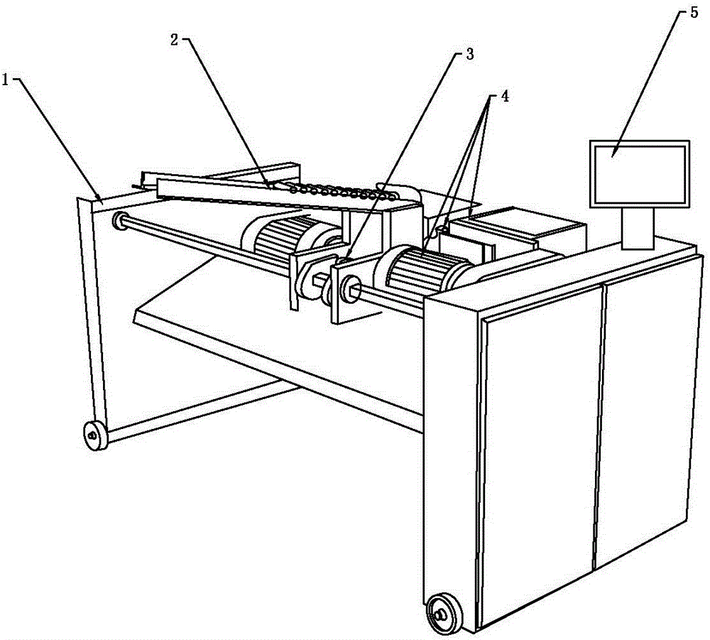
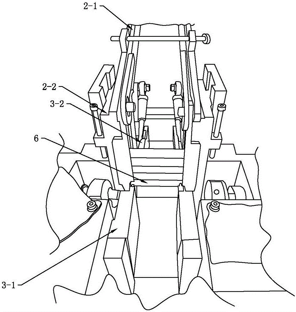
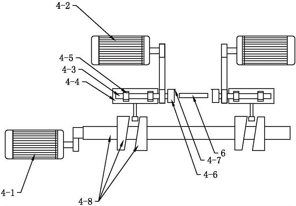
[0039] The chamfering processing control method of the shaft workpiece 6 in this embodiment is applied to a fully automatic double-head chamfering machine, see Figures 1 to 3 , the fully automatic double-head chamfering machine includes an organic support 1, a feeding mechanism 2, a clamping mechanism 3, a rotary cutting mechanism 4, a light sensing system, an infrared pulse counter, a blanking receiving device and a microcomputer 5, and the feeding mechanism 2 includes There are feed roller table and material guide device, the feed roller table is composed of two feed slats 2-1, the material guide device is composed of two material guide plates 2-2 respectively provided with feed grooves, the two guide plates The feed plate 2-2 is fixed on the body support 1, the feed track communicates with the feed trough and the side wall at the bottom of the feed trough is provided with a feed trough outlet.

[0040] The clamping mechanism 3 includes a clamping fixed block 3-1, a clampin...

Embodiment 2

[0054] The main technical solution of this embodiment is basically the same as that of Embodiment 1, and the features not explained in this embodiment are explained in Embodiment 1, and will not be repeated here. In step (4), the forward and backward driving motor drives the cutterhead to advance 12mm at a speed of 1000mm / min. In step (5), the forward and backward drive motor drives the cutter head to retreat 8mm at a speed of 1000mm / min.

Embodiment 3

[0056] The main technical solution of this embodiment is basically the same as that of Embodiment 1, and the features not explained in this embodiment are explained in Embodiment 1, and will not be repeated here. The advance and retreat drive motor drives the cutterhead to advance 18mm at a speed of 1000mm / min, and in step (5), the advance and retreat drive motor drives the cutterhead to withdraw 12mm at a speed of 1000mm / min.


PUM


Abstract

The invention discloses a chamfering machining control method for axle workpieces. A microcomputer is used for controlling running of components of a chamfering machine, multiple photosensitive sensors are utilized for determining whether the workpieces are arranged in place or not, detection on the shapes of the end faces of the workpieces happens before the workpieces fall to the clamping position, the end face shapes obtained through detection are recognized by the microcomputer through photovoltaic conversion, and accordingly the rotating speed of a cutting spindle and the feeding speed of a blade are controlled in combination with the material trademark of the workpieces. On the other hand, a feeding detection sensor is used for detecting a feeding station of a feeding roller table and sending information about whether the workpieces exist or not to the microcomputer, wherein if no workpieces exist, equipment is reminded of material supplementing, pausing or standby is conducted, the equipment is prevented from idling for a long time, and running energy consumption of a production line is reduced. Meanwhile, a light sensation counter is utilized for automatically counting the number of the chamfered workpieces and transmitting data to the microcomputer, quantitative production is achieved, the later counting workload is reduced, and quantitative conveying and packaging are convenient.

Description

technical field [0001] The invention relates to the technical field of chamfering processing, in particular to a control method for chamfering processing of shaft workpieces. Background technique [0002] With the rapid development of my country's industry, the demand for high-strength fastener products known as "industrial rice" is increasing. With the continuous deepening of reforms in the country and the upgrading of enterprise transformation, the prices of raw materials and labor costs continue to rise. The competition of the company's products brings enormous pressure. Shaft workpieces, especially the chamfering of high-strength bolts, the current situation is that although the manual chamfering instrument lathe equipment is cheap and easy to operate, the production efficiency is low, the production quality is difficult to guarantee, and the labor intensity is high. The price of the semi-automatic chamfering machine is moderate, and the production The efficiency is grea...

Claims


Application Information

Patent Timeline
Patent Type & Authority Applications(China)
IPC IPC(8): B23C3/12
CPCB23C3/12
Inventor 杨东生李大明黄文华李卫清赵亚高李月明邓雪雅
Owner GUANGDONG MINGHAO HIGH STRENGTH FASTENERS
Why Eureka
Try Eureka