Circular tube intersecting line cutting production line

A technology of intersecting wire cutting and production line, applied in welding equipment, laser welding equipment, metal processing equipment, etc., can solve the problems of high labor intensity and low efficiency, and achieve the effect of improving production efficiency

Inactive Publication Date: 2017-05-17
CHANGZHOU COLLEGE OF INFORMATION TECH
View PDF5 Cites 12 Cited by
  • Summary
  • Abstract
  • Description
  • Claims
  • Application Information

AI Technical Summary

Problems solved by technology

[0003] The traditional round pipe cutting adopts manual loading, manual clamping, and manual unloading, which is labor-intensive and low-efficiency, which does not match the high-efficiency characteristics of laser cutting.

Method used


Image

  • Circular tube intersecting line cutting production line

Examples


Embodiment Construction

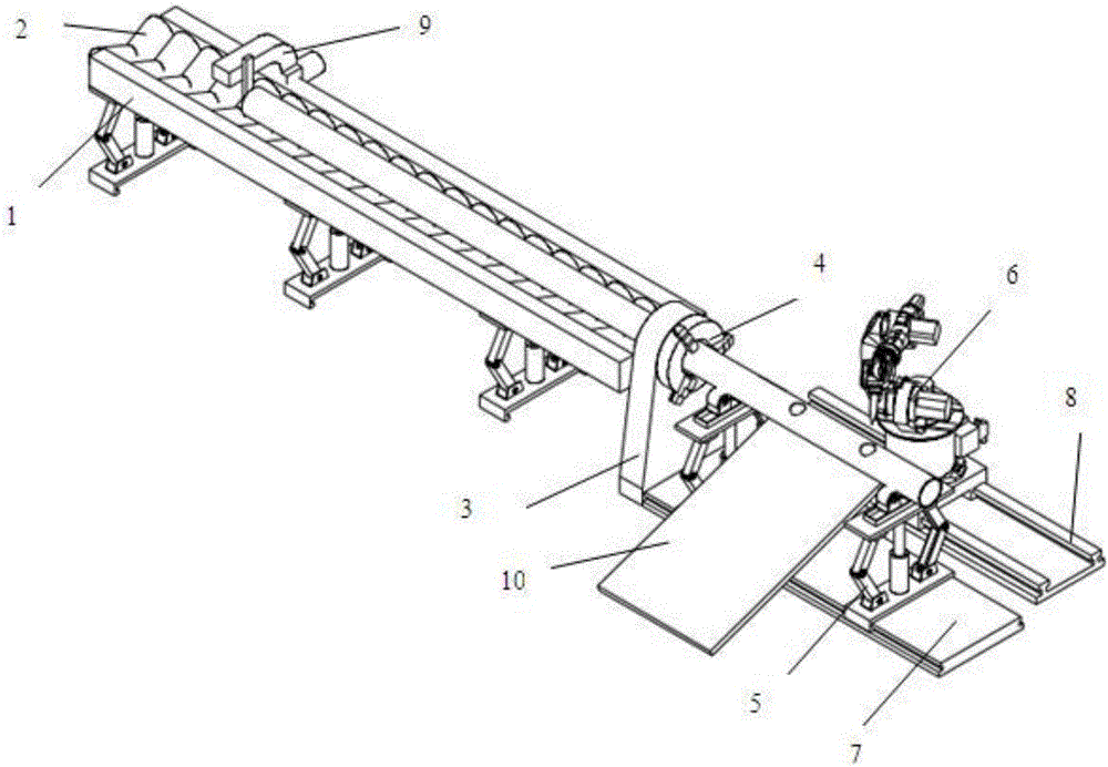
[0014] Attached below figure 1 Description, a circular tube intersecting wire cutting production line, including a feeding part for feeding round tube materials, a cutting part and a blanking part for finished product blanking, the feeding part includes a lifting platform 1 and a 1 on the round pipe transfer device; the cutting part includes a positioner 3, a hollow chuck 4, a liftable bracket 5 and a laser cutting robot 6, and the hollow chuck 4 is installed on the positioner 3, The center of the rotary unit of the positioner 3 has a round hole through which the material of the round tube can pass, and the center of rotation of the hollow chuck 4 coincides with the center of rotation of the rotary unit of the positioner 3, forming a channel for feeding the material of the round tube; There are two liftable brackets 5. When cutting the round tube material, the liftable bracket 5 rises to support the round tube material; The height is lower than the height of the rotation cent...


PUM


Abstract

The invention discloses a circular tube cutting device. The circular tube cutting device comprises a feeding part, a cutting part and a discharging part, and is mainly composed of a lifting conveying platform, a dislodgement machine, a hollow chuck, liftable brackets, a laser cutting robot and a slope discharging rolling path; automatic feeding, cutting and discharging of circular tubes can be achieved; and the circular tube cutting device can adapt to different tube diameters, the production efficiency can be greatly improved, and the manpower cost is reduced.

Description

technical field [0001] The invention relates to a material laser cutting device, in particular to a cutting device for circular tube materials. Background technique [0002] Laser cutting is to use a focusing mirror to focus the laser beam on the surface of the material to melt the material, and at the same time use the compressed gas coaxial with the laser beam to blow away the melted material, and make the laser beam and the material move relative to each other along a certain trajectory, thus forming a certain Shape slits. Laser cutting technology is widely used in the processing of metal and non-metal materials, which can greatly reduce processing time, reduce processing costs and improve workpiece quality. [0003] The traditional round pipe cutting adopts manual loading, manual clamping, and manual unloading, which is labor-intensive and low-efficiency, which does not match the high-efficiency characteristics of laser cutting. Contents of the invention [0004] Pur...

Claims


Application Information

Patent Timeline
Patent Type & Authority Applications(China)
IPC IPC(8): B23K26/38B23K26/70
CPCB23K26/38B23K26/702
Inventor 陈军华
Owner CHANGZHOU COLLEGE OF INFORMATION TECH
Why Eureka
Try Eureka