A connection device for an electric welding machine

A connection device and electric welding machine technology, applied in welding equipment, auxiliary equipment, auxiliary welding equipment, etc., can solve the problems of increased difficulty in taking and discharging wires, cumbersome operations, electric shock accidents, etc., to improve space utilization efficiency and work efficiency , the effect of reducing the floor area

Active Publication Date: 2018-11-09
江苏南洋电子有限公司
View PDF4 Cites 0 Cited by
  • Summary
  • Abstract
  • Description
  • Claims
  • Application Information

AI Technical Summary

Problems solved by technology

[0002] At present, electric welding machines are widely used in some electric welding factories. During welding, some welding objects are large and difficult to move, so it is necessary to move the electric welding machine to the welding position. However, the length of the connecting wires of the existing electric welding machines is limited. The wires are short and difficult to plug into the power supply socket. In the existing one or more plug boards are generally used to lengthen the connection, which makes the operation cumbersome and makes it more difficult to take and discharge the wires. At the same time, because there are many plug connectors, artificial Accidental trampling can easily lead to electric shock accidents, and there is a great potential safety hazard

Method used


Image

  • A connection device for an electric welding machine
  • A connection device for an electric welding machine
  • A connection device for an electric welding machine

Examples


Embodiment Construction

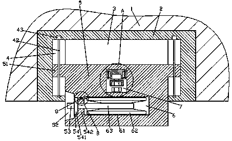
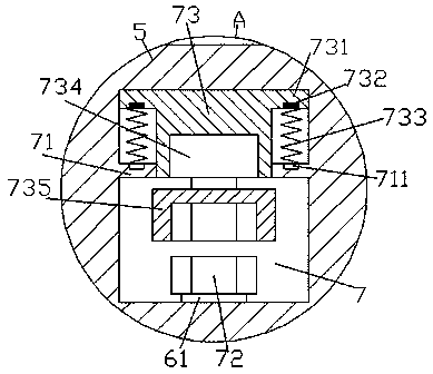
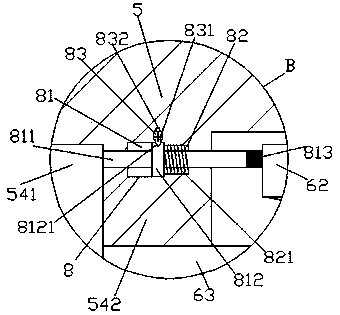
[0020] Such as Figure 1-Figure 6 As shown, a connection device for an electric welding machine of the present invention includes a wall 1 and a stand 2 arranged in the wall 1 , the inner bottom of the stand 2 is provided with a cavity 3 , and the inside of the cavity 3 A sliding piece 5 is provided, and a control area 52 is arranged in the outer wall on the left side of the sliding piece 5, and a placement groove 54 is arranged in the sliding piece 5 on the right side of the manipulation area 52, and the placement groove 54 is arranged on the right side. A first hollow cavity 6 is provided in the sliding member 5 on the side, and a first baffle plate 542 is provided between the first hollow cavity 6 and the placement groove 54, and all the above the first hollow cavity 6 The sliding member 5 is provided with a second hollow cavity 7, and a second baffle plate 71 is provided in the second hollow cavity 7, and a protrusion is provided in the second hollow cavity 7 above the sec...


PUM


Abstract

The invention discloses an electric welding machine connecting device which comprises a wall body and a frame base arranged in the wall body. A cavity is arranged at the bottom in the frame base, a slippage part is arranged in the cavity, a control zone is arranged in the outer wall of the left side of the slippage part, a placement groove is formed in the slippage part on the right side of the control zone, a first hollow cavity is formed in the slippage part on the right side of the placement groove, a first baffle is arranged between the first hollow cavity and the placement groove, a second hollow cavity is formed in the slippage part above the first hollow cavity, a first baffle is arranged in the second hollow cavity, a boss is arranged in the second hollow cavity above the first baffle, protruding blocks are arranged at the tops of two sides of the boss, magnets are arranged in the bottoms of the protruding blocks, magnets are arranged in the bottoms of the protruding blocks, electromagnetic coil devices are arranged at the top of the first baffle corresponding to the magnets, first compression springs are arranged between the electromagnetic coil devices and the magnets, and the bottom of the boss penetrates through the first baffle. The electric welding machine connecting device is simple in structure, convenient to operate, small in occupied area and capable of meeting wiring demands of different distances and achieving wire take-up work, and the working efficiency is improved.

Description

technical field [0001] The invention relates to the field of welding technology, in particular to an electric welding machine connecting device. Background technique [0002] At present, electric welding machines are widely used in some electric welding factories. During welding, some welding objects are large and difficult to move, so it is necessary to move the electric welding machine to the welding position. However, the length of the connecting wires of the existing electric welding machines is limited. The wires are short and difficult to plug into the power supply socket. In the existing one or more plug boards are generally used to lengthen the connection, which makes the operation cumbersome and makes it more difficult to take and discharge the wires. At the same time, because there are many plug connectors, artificial Accidental trampling can easily lead to electric shock accidents, and there is a great potential safety hazard. Contents of the invention [0003]...

Claims


Application Information

Patent Timeline
Patent Type & Authority Patents(China)
IPC IPC(8): B65H75/38
CPCB23K37/00
Inventor 王丹
Owner 江苏南洋电子有限公司
Why Eureka
Try Eureka