A chemical-mechanical grinding device with no rotating end point

A chemical machinery and grinding device technology, applied in the direction of grinding devices, grinding machine tools, metal processing equipment, etc., can solve the problems of excessive movement of the grinding head, production capacity impact, cable damage logic, etc., to reduce design difficulty and high utilization efficiency , to avoid the effect of no-load phenomenon

Active Publication Date: 2018-11-09
SHANGHAI INTEGRATED CIRCUIT RES & DEV CENT
View PDF6 Cites 0 Cited by
  • Summary
  • Abstract
  • Description
  • Claims
  • Application Information

AI Technical Summary

Problems solved by technology

One of the disadvantages of this arrangement is that the grinding head cannot be moved continuously in one direction, i.e. the grinding head cannot be moved more than the length of the cable
When the moving distance of the grinding head is too long, it must return to the original point and move again. The possible problem is that each grinding head will have a period of no-load operation to return to the original point every once in a while, and the accumulation of time will also affect the production capacity.
The second disadvantage is the limitation of the space on the top of the machine table for cable laying. Cable laying requires to avoid mutual interference between cables and have enough stretching space. As a result, the current number of grinding heads is generally about 4, at most 6
At the same time, if due to misoperation, it may also cause excessive movement of the grinding head, damage the cable and cause logic confusion, and eventually cause shutdown

Method used


Image

  • A chemical-mechanical grinding device with no rotating end point
  • A chemical-mechanical grinding device with no rotating end point
  • A chemical-mechanical grinding device with no rotating end point

Examples


Embodiment Construction

[0029] The specific embodiments of the present invention will be further described in detail below with reference to the accompanying drawings.

[0030] It should be noted that in the following specific embodiments, when the embodiments of the present invention are described in detail, in order to clearly show the structure of the present invention for ease of description, the structure in the drawings is not drawn according to the general scale. Partial enlargement, deformation, and simplification of processing have been implemented. Therefore, this should be avoided as a limitation of the present invention.

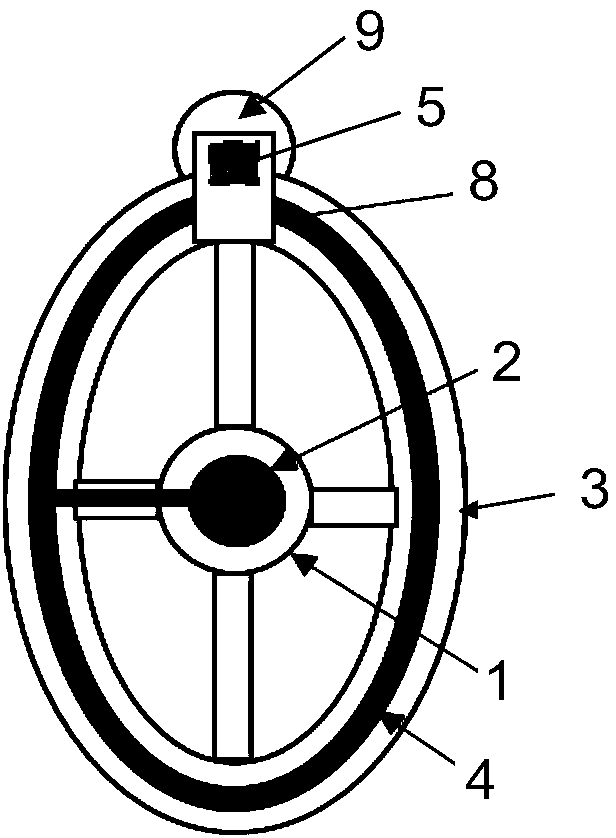
[0031] In the following specific embodiments of the present invention, please refer to figure 1 , figure 1 It is a top view of the structure of a chemical mechanical polishing device without a rotating end point according to a preferred embodiment of the present invention. Such as figure 1 As shown, a chemical mechanical polishing device without a rotation end point of the p...


PUM


Abstract

The invention discloses a chemical mechanical polishing device without a rotation end point. The chemical mechanical polishing device without the rotation end point comprises a polishing head carrying mechanism, a polishing head control assembly, and a non-contact power supply system. The polishing head carrying mechanism comprises a circular railway; the circular railway is fixed with a stand column through a support; the polishing head control assembly is slidably arranged on the outer side of the circular railway; a polishing head control unit for controlling the polishing head control assembly and a polishing head to operate is arranged in the polishing head control assembly; and the non-contact power supply system comprises a power supply part arranged along the circular railway and a current collection part arranged in the polishing head control assembly at a relative clearance. According to the chemical mechanical polishing device without the rotation end point provided by the invention, an existing power transmission way adopting cable connection is changed to a non-contact power transmission way, power is supplied to the power supply part to generate a magnetic field, and a magnetic induction current is generated by the the current collection part and is outputted to the polishing head control unit so as to drive the polishing head control assembly to move along the railway, so that the movement of the polishing head cannot be influenced by the length of a cable, the polishing head can continuously move along one direction without limit, the no-load phenomenon of the polishing head is avoided, and the utilization efficiency of machine table is improved.

Description

Technical field [0001] The present invention relates to the technical field of semiconductor integrated circuit equipment, and more specifically, to a chemical mechanical polishing device without a rotating end point. Background technique [0002] In the semiconductor field, chemical mechanical polishing (CMP) is an indispensable part of the semiconductor process. However, due to technical relations, the output of CMP is relatively low compared with the process equipment at its front and rear sites. This is especially evident in the subsequent copper process. [0003] In order to change this status quo, CMP main equipment began to develop in the direction of large-scale and multi-pol ish heads. Correspondingly, the polishing platen has become larger, and the size of the polishing pad has also increased to 42 inches or even larger, making space management more complicated. [0004] At the same time, the production capacity of CMP is lower than that of the previous site ECP (electrop...

Claims


Application Information

Patent Timeline
Patent Type & Authority Patents(China)
IPC IPC(8): B24B37/005B24B37/00
CPCB24B37/00B24B37/005
Inventor 戴文俊
Owner SHANGHAI INTEGRATED CIRCUIT RES & DEV CENT
Why Eureka
Try Eureka