
Kitchen waste oil-water separation apparatus and oil-water separation method thereof

A technology of waste oil and separation device, applied in separation method, oil/oily substance/float removal device, liquid separation, etc., can solve the problem of low oil recovery rate of kitchen waste and single oil-water separation technology separation The problem is that the effect is low and the oil in the water is enriched, so as to improve the oil-water separation effect, improve the oil-water separation rate, and improve the oil recovery rate.

Pending Publication Date: 2017-05-17
GUANGDONG TESTING INST OF PROD QUALITY SUPERVISION
View PDF6 Cites 2 Cited by
  • Summary
  • Abstract
  • Description
  • Claims
  • Application Information

AI Technical Summary

Problems solved by technology

Large pieces of solid animal fats (such as agglomerated tallow, etc.) that adhere to the surface of solid-phase kitchen waste are difficult to dissolve, so they cannot be formed into liquid oil to be put into subsequent deep processing links, thus making the kitchen waste Grease recycling rate is not high
And kitchen waste oil is mostly composed of fatty acid triglycerides, so it has stronger polarity than mineral oil, so it is more difficult to separate from water
[0004] At present, the existing oil-water separation devices and methods all focus on removing the oil in the water, rather than enriching the oil in the water
In addition, the separation effect of a single oil-water separation technology is generally low

Method used


Image

  • Kitchen waste oil-water separation apparatus and oil-water separation method thereof

Examples


Embodiment Construction

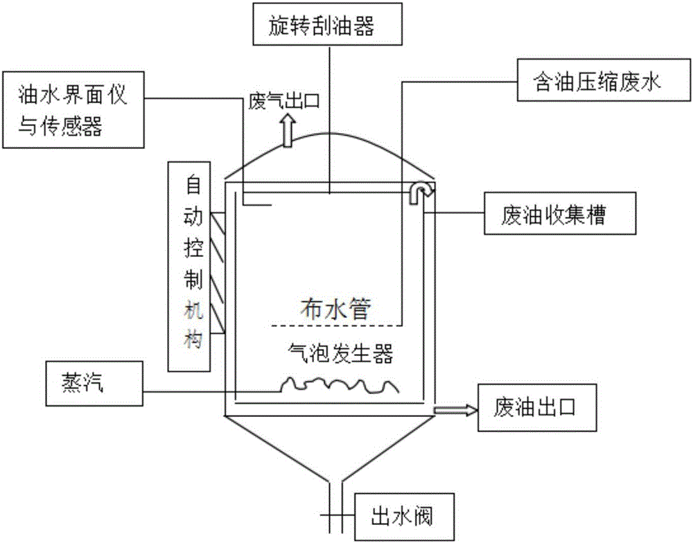
[0028] Such as figure 1 As shown, the kitchen waste oil-water separation device provided in this embodiment includes a vertical tank for storing oil-containing compressed waste water, and the inside of the tank is equipped with an oil-water interface measuring instrument, a temperature sensor, a rotary oil scraper, waste oil Collection tank; the top of the tank is provided with a waste water inlet and a waste gas outlet, the waste water inlet is connected to a water distribution pipe for oily compressed waste water to pass into the tank, and the waste gas outlet is used to connect to the deodorization system of the biological filter; the side of the tank body The bottom of the wall is provided with a steam inlet and a waste oil outlet connected to the waste oil collection tank. A micro-bubble generator connected to the steam inlet is provided inside the tank. The steam generates bubbles through the micro-bubble generator to compress the oil contained in the tank. The oil in th...


PUM


Abstract

The invention discloses a kitchen waste oil-water separation apparatus. The kitchen waste oil-water separation apparatus comprises a vertical tank body, wherein an oil-water interface measurement instrument, a temperature sensor, a rotating oil scraper and a waste oil collection groove are arranged inside the tank body; a waste water inlet and a waste gas outlet are formed in the top of the tank body; a steam inlet and a waste oil outlet communicated with the waste oil collection groove are formed in the bottom of the side wall of the tank body, a micro-bubble generator connected with the steam inlet is also arranged inside the tank body, and bubbles are generated from steam by virtue of the micro-bubble generator to enable an oil component of oil-containing compressed waste water in the tank body to float; the floating oil component is scraped by the rotating oil scraper into the waste oil collection groove and then discharged by virtue of the waste oil outlet; and the bottom of the tank body is provided with a water outlet valve, the oil-water separation apparatus is also provided with an automatic control mechanism, and the automatic control mechanism is respectively electrically connected with the oil-water interface measurement instrument, the temperature sensor and the micro-bubble generator so as to automatically control the oil-water separation. The invention also discloses a method for separating oil and water of kitchen wastes by utilizing the kitchen waste oil-water separation apparatus.

Description

technical field [0001] The invention relates to the field of separation devices, in particular to a kitchen waste oil-water separation device and an oil-water separation method thereof. Background technique [0002] With the rapid development of my country's social economy and the continuous improvement of people's living quality, the amount of kitchen waste is also increasing day by day. Most of them become kitchen waste and have not been effectively recycled, which not only seriously affects the urban environment but also causes serious damage Waste of resources and many food safety hazards, among which the food safety problems caused by kitchen waste oil (ie waste oil) are the most prominent. Slurry kitchen waste with extremely high water content can be separated and collected after the oil-water separation treatment, that is, the deoiling process is completed before it can enter the subsequent deep processing process. Therefore, oil-water separation treatment occupies a ...

Claims


Application Information

Patent Timeline
IPC IPC(8): C02F1/02C02F1/24C02F1/20C02F1/40
CPCC02F1/02C02F1/20C02F1/24C02F1/40
Inventor 陈锦汉唐穗平陈满英张太平廖桂福路风辉扈华庚
Owner GUANGDONG TESTING INST OF PROD QUALITY SUPERVISION
Learn More