RTK technology-based precise locating system piling machine

A technology of precise positioning and piling machine, applied in sheet pile wall, foundation structure engineering, drilling equipment, etc., can solve the problems of complex structure, many parts, and inconvenient operation.

Active Publication Date: 2017-05-17
无锡汉欣利建筑机械有限公司
View PDF6 Cites 8 Cited by
  • Summary
  • Abstract
  • Description
  • Claims
  • Application Information

AI Technical Summary

Problems solved by technology

[0002] At present, there are two types of piling machines used on construction sites: one is a rotary piling machine, the structure of which is a drill pipe suspension frame pulled up by a hoist, and the drill pipe is used to drill holes; the other is an impact hammer Pile driver, the structure of this kind of pile driver is to use the hoist to pull up the impact hammer to repeatedly drop and lift to realize piling. The two piling methods have their own advantages and disadvantages, but both piling machines have the following problems: the drill pipe is inconvenient to assemble and disassemble, and the drill The connection between the rod and the grouting mechanism is not convenient enough to disassemble and assemble, the stability is poor, the drill pipe transportation is not convenient enough, and the operation is not convenient enough. Patent CN105484262A proposes a new type of pile driver. Good frame stability, easy disassembly and assembly of the drill pipe, easy disassembly and assembly of the joint between the drill pipe and the grouting mechanism, good stability, convenient drill pipe transportation, convenient operation, and high safety, but its structure is complex, with many parts and components, and maintenance is difficult. Inconvenient, high cost, so we propose a precise positioning system pile driver based on RTK technology

Method used


Image

  • RTK technology-based precise locating system piling machine
  • RTK technology-based precise locating system piling machine

Examples


Embodiment Construction

[0016] The following will clearly and completely describe the technical solutions in the embodiments of the present invention with reference to the accompanying drawings in the embodiments of the present invention. Obviously, the described embodiments are only some, not all, embodiments of the present invention.

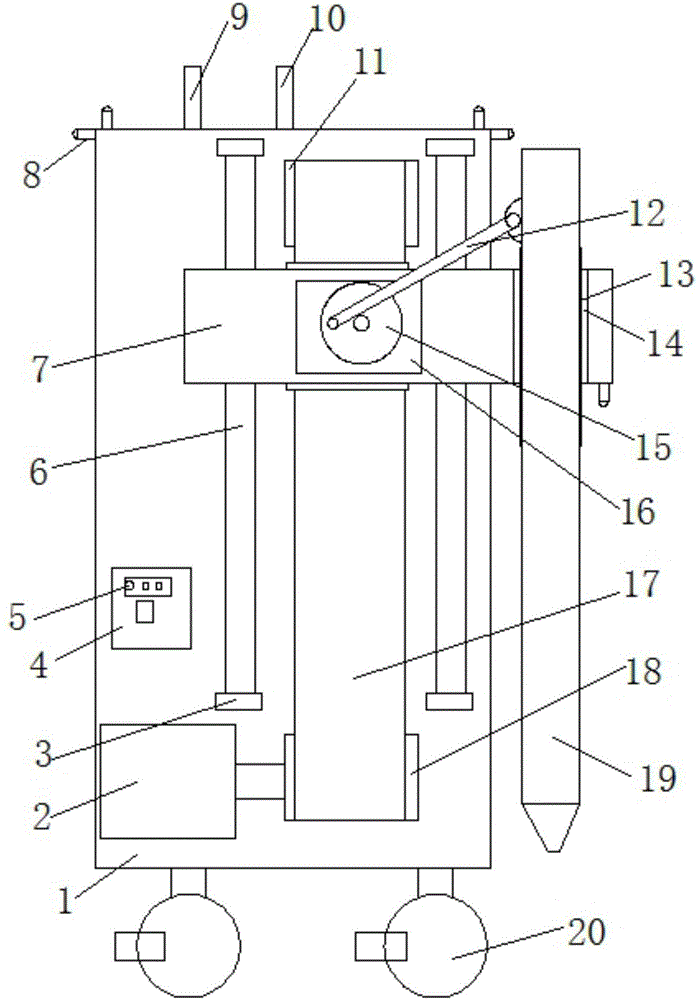
[0017] refer to Figure 1-2 , a pile driver with precise positioning system based on RTK technology, comprising a body 1, a wireless transmitter 9 and a wireless receiver 10 are arranged on the top of the body 1, a driven roller 11 is arranged on the top of the side wall of the body 1, and the side of the body 1 The wall is provided with two vertically arranged first slide rails 6, and the first slide rail 6 is provided with a horizontally arranged movable frame 7, and the side of the movable frame 7 near the first slide rail 6 is provided with two vertically arranged first slide rails. One slide block, the first slide rail 6 is matched with the first slide rail, the...


PUM


Abstract

The invention discloses an RTK technology-based precise locating system piling machine which comprises a machine body, wherein a wireless emitter and a wireless receiver are arranged at the top end of the machine body, wherein a driven roller is arranged at the top end of the side wall of the machine body; two perpendicularly arranged first sliding rails are arranged on the side wall of the machine body; a horizontally arranged movable frame is arranged on the first sliding rails; two perpendicularly arranged first sliding blocks are arranged on one side, close to the first sliding rails, of the movable frame; the first sliding blocks are matched with the first sliding rails; an engine is arranged at the bottom ends of the first sliding rails; an output shaft of the engine is connected with a driving roller; the driving roller is located below the two first sliding rails; the driven roller is located above a position between the two first sliding rails; a transmission belt is connected between the driving roller and the driven roller; the movable frame is fixedly mounted on the transmission belt; a first motor is arranged on the movable frame; and the first motor is fixedly mounted on the movable frame through a screw. The RTK technology-based precise locating system piling machine is simple in structure, low in cost, precise in piling location and high in piling efficiency.

Description

technical field [0001] The invention relates to the technical field of pile drivers, in particular to a pile driver with an accurate positioning system based on RTK technology. Background technique [0002] At present, there are two types of piling machines used on construction sites: one is a rotary piling machine, the structure of which is a drill pipe suspension frame pulled up by a hoist, and the drill pipe is used to drill holes; the other is an impact hammer Pile driver, the structure of this kind of pile driver is to use the hoist to pull up the impact hammer to repeatedly drop and lift to realize piling. The two piling methods have their own advantages and disadvantages, but both piling machines have the following problems: the drill pipe is inconvenient to assemble and disassemble, and the drill The connection between the rod and the grouting mechanism is not convenient enough to disassemble and assemble, the stability is poor, the drill pipe transportation is not c...

Claims


Application Information

Patent Timeline
Patent Type & Authority Applications(China)
IPC IPC(8): E02D7/00E02D13/04E21B17/00
CPCE02D7/00E02D13/04E21B17/00
Inventor 周仕鹏
Owner 无锡汉欣利建筑机械有限公司
Why Eureka
Try Eureka