Low-speed motor direct driving mechanism used for top part driving well drilling device

A low-speed motor and drive mechanism technology, which is applied in the direction of drilling drive devices, drilling equipment, electromechanical devices, etc. The effect of reducing the failure rate, reducing the number of accessory parts, and reducing the number of times of positioning

Inactive Publication Date: 2014-02-26
SOUTHEAST UNIV
View PDF4 Cites 9 Cited by
  • Summary
  • Abstract
  • Description
  • Claims
  • Application Information

AI Technical Summary

Problems solved by technology

The structure of the gearbox is relatively complex, the overload capacity is poor, and the related lubrication and cooling facilities are required, resulting in a high overall failure rate of the top drive
For ordinary AC motors, frequency converters can be used to realize the low-speed operation of the top drive system, but the dynamic characteristics of the motor and frequency converter become worse during low-frequency operation, the high-order harmonics are serious, and the output voltage waveform is severely distorted, causing motor torque ripple and motor heat, and it is easy to interfere with peripheral equipment

Method used


Image

  • Low-speed motor direct driving mechanism used for top part driving well drilling device
  • Low-speed motor direct driving mechanism used for top part driving well drilling device

Examples


Embodiment Construction

[0022] The present invention will be further described below in conjunction with the accompanying drawings.

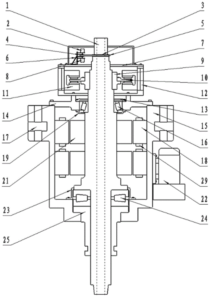
[0023] Such as figure 1 Shown is a low-speed motor direct drive mechanism for a top drive drilling device, including a hollow main shaft 1, a motor and a control mechanism.

[0024] The motor includes a motor upper cover 14, a motor housing 15, a rotary head inner sleeve 25 and a stator-rotor mechanism. 1 Outer side; the outer edge of the motor upper end cover 14 is sealed and fixed with the upper end outer edge of the motor housing 15, the inner edge of the motor upper end cover 14 is connected to the hollow main shaft 1 through the upper end bearing 16, and the connecting part between the motor upper end cover 14 and the hollow main shaft 1 Sealed by the upper end seal; the lower end of the rotary head inner sleeve 25 passes through the lower port of the motor housing 15 and extends out, the upper end of the rotary head inner sleeve 25 engages with the lower end of ...


PUM


Abstract

The invention discloses a low-speed motor direct driving mechanism used for a top part driving well drilling device. The low-speed motor direct driving mechanism comprises a hollow main shaft, a motor and a control mechanism. The motor comprises a motor upper end cover, a motor shell, a rotation head internal sleeve and a stator and rotor mechanism. The motor upper end cover, the motor shell and the rotation head internal sleeve are all sleeved on the external side of the hollow main shaft. The stator and rotor mechanism is installed in a sealing space formed by the motor upper end cover, the motor shell and the hollow main shaft. The sealing space is communicated with a cold air mechanism. The stator and rotor mechanism has a protruding-pole structure and is designed in a two-segment type. The control mechanism comprises a speed monitoring device and a brake device which is arranged on the hollow main shaft. According to the low-speed motor direct driving mechanism used for the top part driving well drilling device, the hollow main shaft is utilized to directly drive a drilling rod without an intermediate speed reducing mechanism so that structure of the top part driving well drilling device is greatly simplified, and a large amount of auxiliary components are reduced. Meanwhile, the well drilling process becomes smoother by structural design of the motor.

Description

technical field [0001] The invention relates to a top drive drilling device, in particular to a low-speed motor direct drive mechanism for the top drive drilling device, which belongs to the technology of oil and gas drilling rigs. Background technique [0002] During the oil and gas drilling process, the top drive drilling device can directly rotate the drill pipe from the upper space of the derrick to complete various drilling operations such as drilling, circulating drilling fluid, connecting columns, making up and breaking out, and back reaming. The top drive drilling unit has significantly improved the safety and efficiency of drilling operations and has become a standard product in the oil drilling industry. [0003] At present, most of the top drive drilling devices are driven by DC motors, AC motors and hydraulic motors. The above top drive devices need to use a gearbox to reduce the speed and increase the torque. The gearbox has a relatively complex structure, poor...

Claims


Application Information

Patent Timeline
Patent Type & Authority Applications(China)
IPC IPC(8): H02K7/116E21B4/04
Inventor 胡敏强仲伟波余海涛黄磊刘强刘春元闻程陈中显
Owner SOUTHEAST UNIV
Why Eureka
Try Eureka