Controllable-temperature communication machine room convenient to maintain

A communication equipment room and equipment room technology, which is applied in the control input, ventilation system, mechanical equipment and other directions involving air characteristics, can solve the problems of waste of resources, easy destruction of the communication equipment room, equipment failure, etc., so as to prevent malicious damage and save ground resources. , the effect of high feasibility

Active Publication Date: 2017-05-17
安徽靖科机电有限公司
View PDF8 Cites 6 Cited by
  • Summary
  • Abstract
  • Description
  • Claims
  • Application Information

AI Technical Summary

Problems solved by technology

[0004] The biggest problems faced by the existing communication equipment room are: 1. The communication equipment room is generally built next to the communication tower, which occupies a large area and wastes resources
2. The communication room is easily damaged due to daily unattended
3. Due to the heat generated by the equipment in the communication room, when the heat cannot be dissipated in time, it will lead to equipment failure

Method used


Image

  • Controllable-temperature communication machine room convenient to maintain
  • Controllable-temperature communication machine room convenient to maintain
  • Controllable-temperature communication machine room convenient to maintain

Examples


Embodiment Construction

[0030] The present invention is described in further detail now in conjunction with accompanying drawing. These drawings are all simplified schematic diagrams, which only illustrate the basic structure of the present invention in a schematic manner, so they only show the configurations related to the present invention.

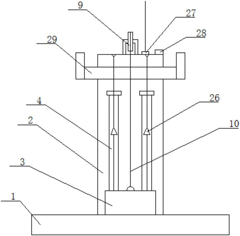
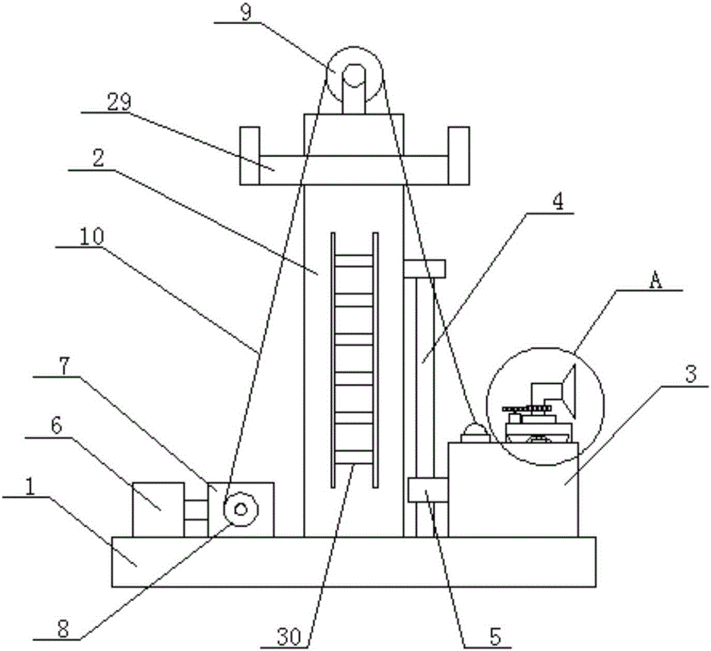
[0031] like Figure 1-6 As shown, a temperature-controllable communication machine room that is easy to maintain includes a base 1, a mast 2, a machine room 3, a lifting mechanism, a hidden mechanism, a shielding mechanism, and an air intake mechanism;

[0032] The tower mast 2 is vertically arranged on the base 1, and one side of the tower mast 2 is provided with a guide rod 4, and the guide rod 4 is vertically arranged. There are two guide rods 4, two guide rods 4 are symmetrically arranged, a slider 5 is provided on one side of the machine room 3, and a through hole is provided on the slider 5, and the through hole is a vertical through hole. There are two...


PUM


Abstract

The invention relates to a controllable-temperature communication machine room convenient to maintain. The controllable-temperature communication machine room comprises a base, a tower mast, a machine room body, a lifting mechanism, a concealing mechanism, a shielding mechanism and an air inlet mechanism. The lifting mechanism comprises a lifting motor, a reduction box, a take-up device, a fixed pulley and a pull rope. The concealing mechanism comprises a bottom plate, a spring and electromagnets. The shielding mechanism comprises a first motor and a turnplate. The air inlet mechanism comprises an air inlet hood, an air inlet tube, an air inlet hopper, a second motor, a first circular gear and a second circular gear. According to the controllable-temperature communication machine room convenient to maintain, the lifting mechanism is capable of enabling the machine room body to rise and fall and to be fixed stably at any height, the ground resource is saved, and the machine room body is prevented from being damaged maliciously; through the air inlet mechanism, air can be guided into the machine room body; the shielding mechanism can be used for controlling the air inlet quantity; the concealing mechanism can control the air outlet quantity; and through cooperative use of the air inlet mechanism, the shielding mechanism and the concealing mechanism, the ventilating property of the machine room body can be controlled, and accordingly the temperature in the machine room body is controlled.

Description

technical field [0001] The invention relates to the field of communication equipment rooms, in particular to a temperature-controllable communication equipment room which is convenient for maintenance. Background technique [0002] Communication base station, also known as wireless base station, refers to a low-power wireless antenna that communicates with user mobile phones. According to the size of its service area and the number of users, the transmission power varies from a few watts to hundreds of watts. Generally, base station antennas are installed on buildings or transmission towers 15-50 meters above the ground. [0003] The base station is generally placed in the communication equipment room. Multiple base stations can be located in one equipment room, or one base station can be equipped with one equipment room. [0004] The biggest problems faced by the existing communication equipment room are: 1. The communication equipment room is generally built next to the c...

Claims


Application Information

Patent Timeline
Patent Type & Authority Applications(China)
IPC IPC(8): E04H5/02E04H12/00E04H12/18F24F7/06F24F11/00
CPCE04H5/02E04H12/00E04H12/18F24F7/065F24F11/30F24F11/70F24F2110/00F24F2110/10F24F2110/30
Inventor 施淑琴
Owner 安徽靖科机电有限公司
Why Eureka
Try Eureka