U-shaped steel composite support structure for deep dynamic pressure soft rock roadway and construction method of U-shaped steel composite support structure

A composite support and construction method technology, which is applied in tunnels, tunnel linings, earthwork drilling and mining, etc., can solve the problems that the support cannot play a supporting role in time, the initial support force cannot be applied to the surrounding rock, and the deformation of the surrounding rock can be solved. Economical effect, flexible and changeable support form, and the effect of avoiding local damage

Inactive Publication Date: 2017-05-17
ANHUI UNIV OF SCI & TECH
View PDF10 Cites 42 Cited by
  • Summary
  • Abstract
  • Description
  • Claims
  • Application Information

AI Technical Summary

Benefits of technology

This patented technology solves problems by providing an improved way for protective structures around underground tunnels during mineral exploration operations or other environments where there may be significant movement caused by rocks impacting them over time. By utilizing these technical features, this new method allows for better stability without requiring stronger materials like concrete walls or timber posts.

Problems solved by technology

This patented technology improves upon the use of temporary supports for controlling tunnel walls during heavy work environments like coal mineral extraction (CME) operations. These supports include anchoring systems called tiespersons, punchings, jackets filled with sand, reinforced materials, and other techniques aimed towards providing better support structures while maintaining adequate space around these rocks without causing damage from excessive stress caused by factors like drilling and scraping.

Method used


Image

  • U-shaped steel composite support structure for deep dynamic pressure soft rock roadway and construction method of U-shaped steel composite support structure
  • U-shaped steel composite support structure for deep dynamic pressure soft rock roadway and construction method of U-shaped steel composite support structure
  • U-shaped steel composite support structure for deep dynamic pressure soft rock roadway and construction method of U-shaped steel composite support structure

Examples


Embodiment 1

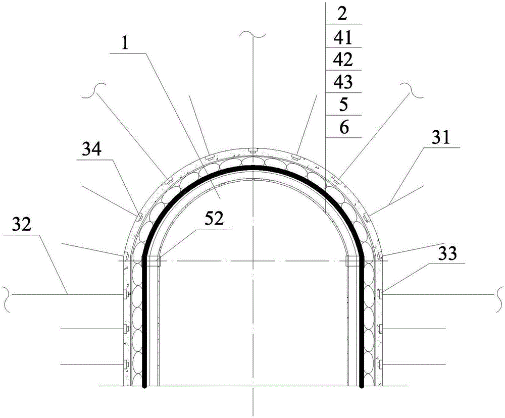
[0056] refer to Figure 1~4 , the construction steps, methods and related parameters are as follows:

[0057] A) Excavate roadway 1 according to the design section shape and size of roadway 1, and spray 50mm thick concrete leveling layer 2 on the section of roadway 1, the design strength is not lower than C20, and the mix ratio is cement: melon seeds: sand: water = 1:2 : 2: 0.45, and mixed with 2.5% cement amount of quick-setting agent;

[0058] B) After the initial setting of the concrete leveling layer, use the anchor rod 31 and the anchor cable 32 to drive into the interior of the surrounding rock 1 and expose it, and fix it with the tray 33 and the nut 34. The specification of the tray 33 used is 150mm×150mm×150mm. Not less than 150kN, the anchor rod 31 used is a high-strength prestressed anchor rod with a diameter of Φ20mm, a total length of 2400mm, a spacing of 700mm, and a row spacing of 700mm. , total length 7000mm, such as figure 1 As shown, one is arranged on the ...

Embodiment 2

[0062] refer to Figure 5 with Image 6 , on the basis of Embodiment 1, if the surrounding rock is relatively broken and accompanied by the phenomenon of undercutting, it is further preferable to add grouting construction equipment and anti-bottom arches, and the increased construction steps, methods and related parameters are as follows:

[0063] E) If Figure 5 As shown, in step B) of Embodiment 1, a plurality of hollow grouting anchor rods 35 and hollow grouting anchor cables 36 are arranged, and the grouting construction is carried out after the roadway 1 is excavated to form a grouting layer 37, inject The slurry material is clay cement slurry;

[0064] F) Excavate 500-600mm downward from the roadway 1 floor, and then drive the anchor rod 31 to the bottom plate of the roadway 1 and fix it with the tray 33 and the nut 34, and lay the latticed steel mesh anti-bottom arch 71, which consists of a diameter of Φ10mm It is made of welded steel bars, and a buffer layer 72 is s...

Embodiment 3

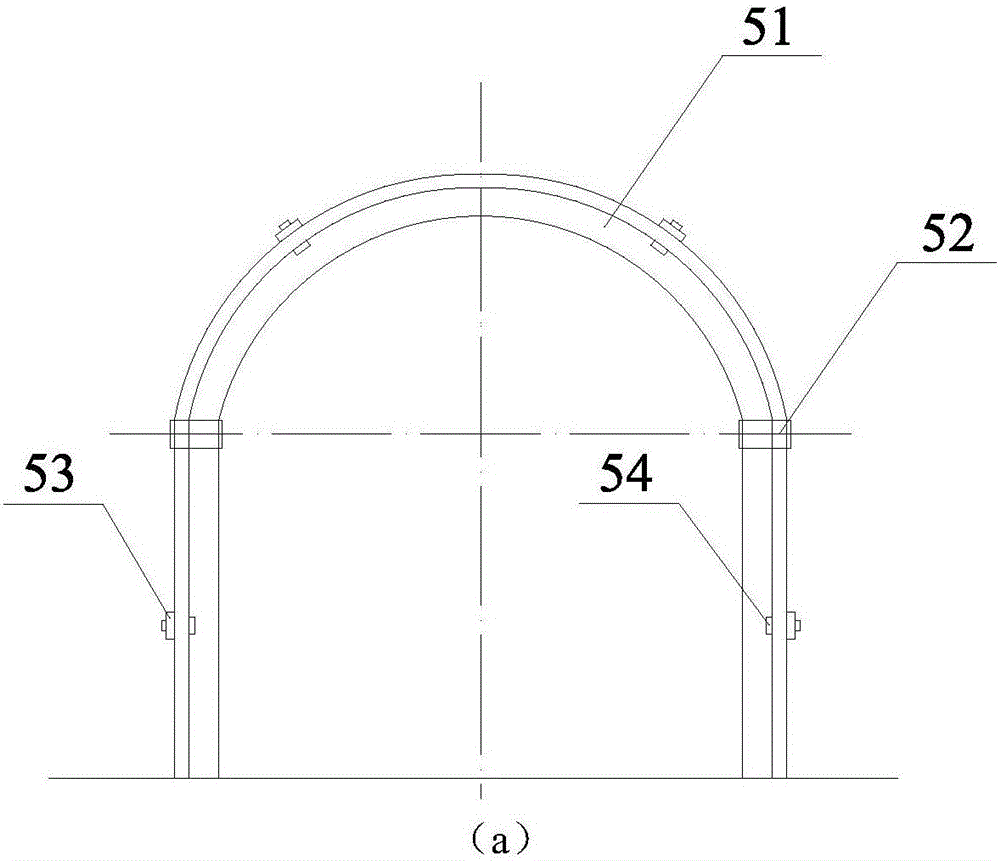
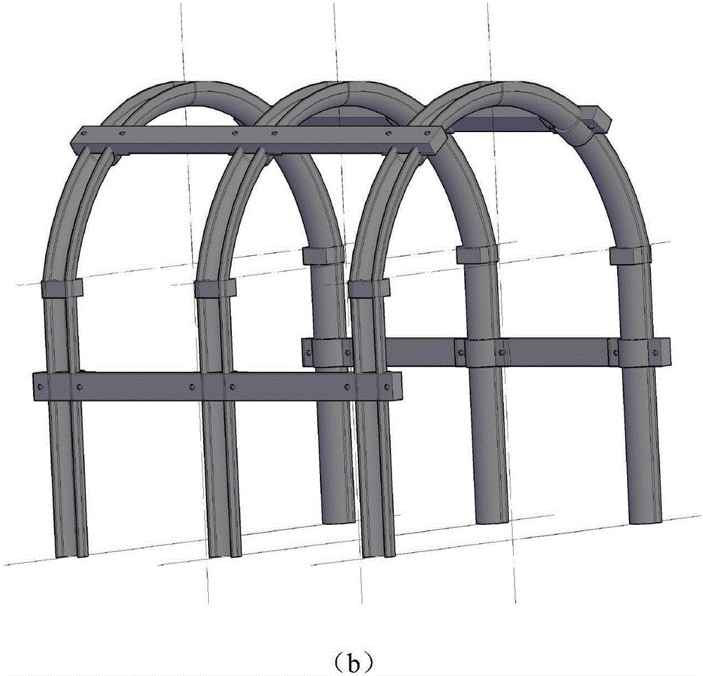
[0068] refer to Figure 7 with Figure 8 , on the basis of Embodiments 1 and 2, if the ground pressure of the vault and the two sides of the roadway 1 is strong and accompanied by large deformation, it is further preferable to add support columns, and the additional construction steps, methods and related parameters are as follows:

[0069] G) support column 8 is set, and support column 8 is steel pipe concrete column, and the diameter of steel pipe is 300mm, and concrete design strength is C30, and mix ratio is cement: melon seed slice: sand: water=1:2:2:0.45, Figure 7 (a), (b), and (c) are respectively the structural schematic diagrams of the support column 8 being an upright column 81, a "Y" shaped column 82 and a "T" shaped column 83.

[0070] Figure 8 Shown is the structural schematic view of the upright column 81 implemented on the present invention.

[0071] In fact, the construction method, steps and relevant parameters are the same as those in Embodiments 1 and 2...


PUM

PropertyMeasurementUnit
Thicknessaaaaaaaaaa
Diameteraaaaaaaaaa
Carrying capacityaaaaaaaaaa

Abstract

The invention discloses a U-shaped steel composite support structure for a deep dynamic pressure soft rock roadway and a construction method of the U-shaped steel composite support structure. The U-shaped steel composite support structure comprises anchor rods, anchor cables, a U-shaped steel support, a uniform pressure relief course, an inverted arch and supporting stand columns. The construction method comprises the steps that firstly, the anchor rods and the anchor cables are driven into surrounding rock; secondly, the U-shaped steel support is erected; and thirdly, the uniform pressure relief layer is arranged between the U-shaped steel support and the roadway surrounding rock, wherein the uniform pressure relief layer comprises a polyester fiber net, filling bodies and a rebar net. If the surround rock where the roadway is located is much broken, the number of surrounding rock grouting equipment can be increased; if a floor heave phenomenon occurs in the roadway, the number of inverted arches can be increased; and if the vault and the two sides of the roadway are intense in ground pressure and deform greatly, the number of supporting stand columns can be increased. The uniform pressure relief layer is additionally arranged on the basis of a common U-shaped steel support structure, the setting load of the support structure is increased through a pressure relief effect of the uniform pressure relief layer, and a high deformation buffering capability is achieved; and meanwhile, a plurality of selectable measures are provided, and the U-shaped steel composite support structure and the construction method thereof can adapt to different stratum conditions, can save the cost, and are remarkable in economic benefit.

Description


Claims


Application Information

Patent Timeline
Owner ANHUI UNIV OF SCI & TECH
Why Eureka
Try Eureka