Hydraulic torsion shock absorber

A torsional shock absorber and shock absorber technology, which is applied in the direction of rotation vibration suppression, etc., can solve problems such as poor corrosion resistance, oil leakage, and poor sealing

Inactive Publication Date: 2017-05-17
杨文元
View PDF0 Cites 0 Cited by
  • Summary
  • Abstract
  • Description
  • Claims
  • Application Information

AI Technical Summary

Problems solved by technology

The existing hydraulic shock absorbers have poor corrosion resistance, complex structure, poor sealing, and many problems such as oil leakage may occur

Method used


Image

  • Hydraulic torsion shock absorber

Examples


Embodiment Construction

[0010] The present invention will be further explained below in conjunction with the accompanying drawings and embodiments.

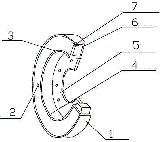
[0011] Such as figure 1 As shown, a hydraulic torsional shock absorber is characterized in that: it includes a U-shaped structure 4; the U-shaped structure 4 is provided with a shock absorber housing 1, and the side of the shock absorber housing 1 is provided with a side cover 3. The side cover 3 is provided with an oil filling screw plug 2; the shock absorber housing 1 is provided with a shock absorber body 7, and the shock absorber body 7 is provided with a torsional vibration system 6, and the shock absorber body 7 is connected with the torsion The vibration system is matched with 6 phases; the shock absorber shell 1 is fixedly connected with the U-shaped metal protection plate 5; the working temperature environment of the hydraulic torsional shock absorber is -20°C-95°C; the static change of the hydraulic torsional shock absorber The ratio is 7.0-1...


PUM


Abstract

The invention discloses a hydraulic torsion shock absorber, which is characterized by comprising a U-shaped structure (4); the U-shaped structure (4) is provided with a shock absorber shell (1), a side cover (3) is arranged at the lateral side of the shock absorber shell (1), and the side cover (3) is provided with an oil filling plug screw (2); a shock absorber body (7) is arranged in the shock absorber shell (1), the shock absorber body (7) is provided with a torsional vibration system (6), and the shock absorber body (7) is adaptive to the torsional vibration system (6); and the shock absorber shell (1) is fixedly connected to a U-shaped metal protective plate (5).

Description

technical field [0001] The invention discloses a shock absorber, in particular to a hydraulic torsion shock absorber. Background technique [0002] Hydraulic shock absorbers are widely used in automobile suspension systems. The principle is that when the frame and the axle move back and forth relative to each other and the piston moves back and forth in the cylinder barrel of the shock absorber, the oil in the shock absorber housing will repeatedly pass through some narrow pores from the inner cavity. into another cavity. At this time, the friction between the liquid and the inner wall and the internal friction of the liquid molecules constitute the damping force for vibration. The hydraulic shock absorber is a new type of shock absorber that has grown up since the 1960s. Its structural feature is that a floating piston is installed at the lower part of the cylinder, and a closed air chamber formed by the floating piston and one end of the cylinder is filled with high-pre...

Claims


Application Information

Patent Timeline
IPC IPC(8): F16F15/12
Inventor 杨文元
Owner 杨文元
Why Eureka
Try Eureka