Hydraulically powered gas injection valve

A gas injection and hydraulic technology, applied in the direction of lift valve, valve device, valve details, etc., can solve the problem of inability to accurately control the opening of the valve core, and achieve the effect of ensuring the relative position, improving the measurement accuracy and improving the reliability of use.

Active Publication Date: 2017-05-17
WEIFANG LICHUANG ELECTRONICS TECH
View PDF11 Cites 3 Cited by
  • Summary
  • Abstract
  • Description
  • Claims
  • Application Information

AI Technical Summary

Problems solved by technology

However, the stroke of the spool has not been tested, so the opening of the spool cannot be precisely controlled

Method used


Image

  • Hydraulically powered gas injection valve
  • Hydraulically powered gas injection valve
  • Hydraulically powered gas injection valve

Examples


Embodiment Construction

[0020] The present invention will be further described below in conjunction with the accompanying drawings and embodiments.

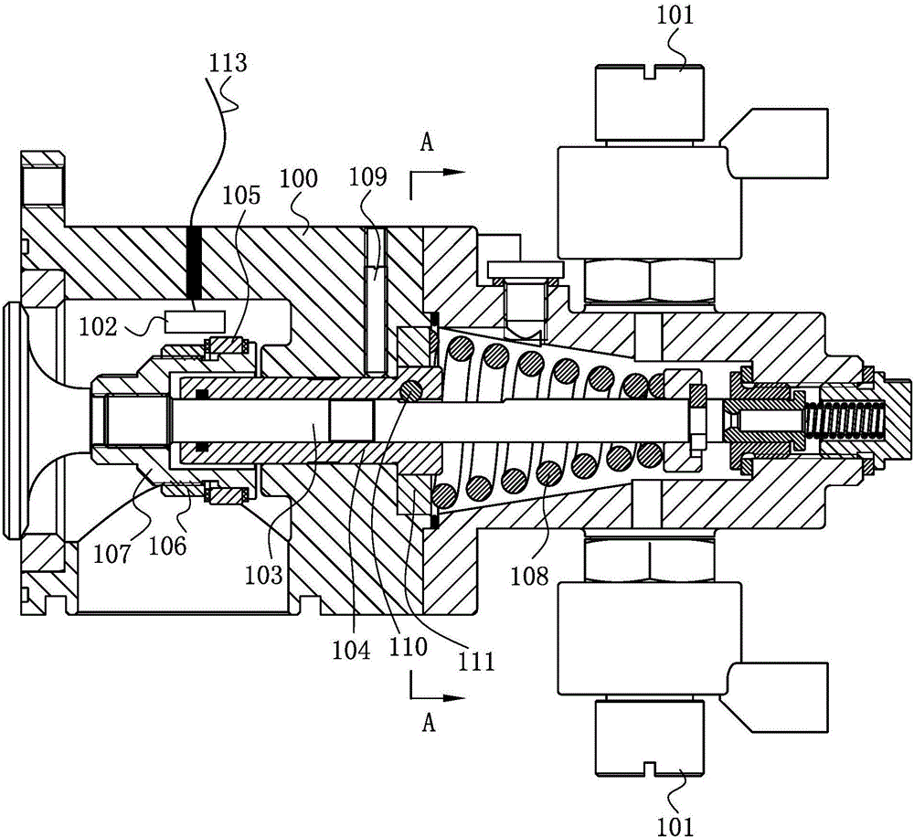
[0021] Such as figure 1 As shown, a hydraulically driven gas injection valve, a solenoid valve 101 is installed outside the valve body 100, through the on-off control of the solenoid valve 101 hydraulic oil enters and exits the valve body cavity, so that the valve core 103 moves, and then opens or closes the injection valve.

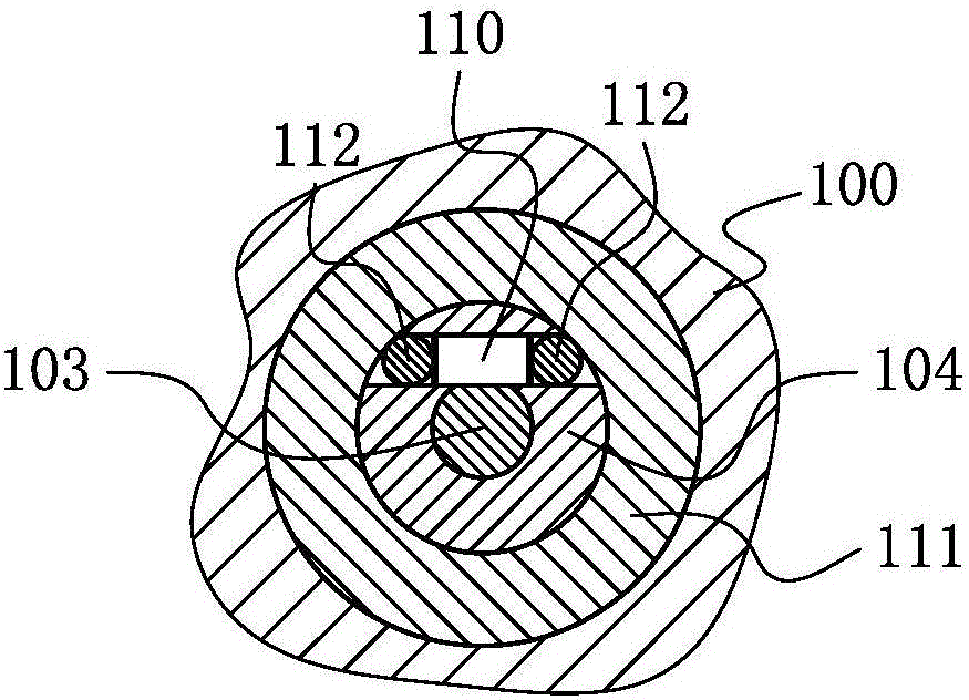
[0022] A valve sleeve 104 is disposed inside the valve body 100 , and a set screw 109 is disposed on the valve body 100 to prevent the valve sleeve from rotating.

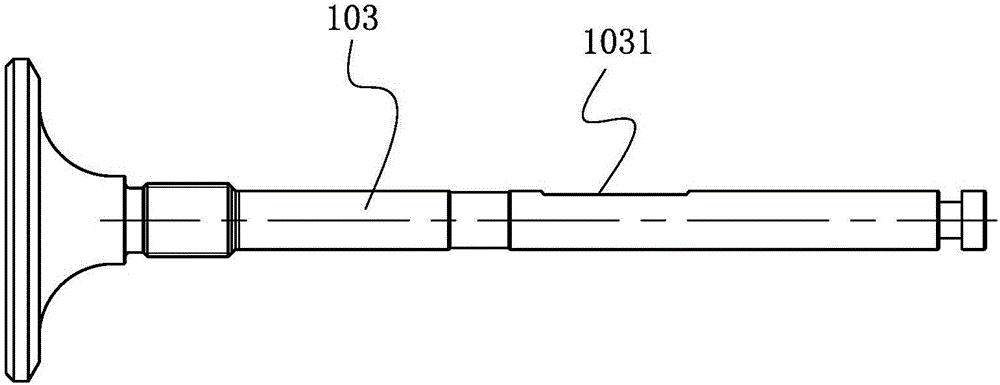
[0023] The valve rod of the valve core 103 is slidingly fitted with the valve sleeve 104 , and the valve rod has a first protruding portion and a second protruding portion protruding from both ends of the valve sleeve 104 respectively. The first protruding part of the valve stem is fixedly connected with a magnet 105 through a magnet seat, and a magnetic field sensor ...


PUM


Abstract

The invention discloses a hydraulically powered gas injection valve which comprises a valve body and a valve element, wherein a valve bush is arranged in the valve body; an electromagnetic valve communicating with an inner cavity of the valve body is mounted at the external part of the valve body; a valve rod of the valve element and the valve bush are in sliding fit; the valve rod is provided with a first stretching part and a second stretching part stretching out of the valve bush; the first stretching part of the valve rod is fixedly connected with a magnet through a magnet seat; a magnetic field sensor is fixed in the valve body and corresponds to the magnet in position; and a sliding guiding device is arranged between the valve rod and the valve bush. The magnet is fixed with the valve element through the magnet seat and moves along with the valve element, and the magnetic field sensor detects variation of a magnetic field to sense the stroke of the valve element so as to accurately control opening of the valve element; and through the sliding guiding device, the valve element is enabled not to rotate during axial movement, so that detection error brought to the magnetic field sensor by magnetism difference of the magnet in the circumferential direction is eliminated, and measurement accuracy is improved.

Description

technical field [0001] The invention relates to the technical field of gas injection valves, in particular to a gas injection valve driven by hydraulic pressure. Background technique [0002] The gas injection valve is a key component of the gas injection system of the internal combustion engine. Chinese utility model patents 201420616390.0, 201520085371.4, 201520673660.6 and 201620890128.4 respectively disclose a gas injection valve, and useful discussions have been made on injection accuracy and reliability. But the stroke of its spool is not detected, so the opening of the spool cannot be accurately controlled. Contents of the invention [0003] Aiming at the above shortcomings of the prior art, the present invention provides a hydraulically driven gas injection valve, which precisely controls the opening of the valve core by detecting the stroke of the valve core. [0004] In order to solve the above technical problems, the technical solution of the present invention...

Claims


Application Information

Patent Timeline
Patent Type & Authority Applications(China)
IPC IPC(8): F16K31/06F02M21/02F16K1/48
CPCF02M21/0218F16K1/48F16K31/0675Y02T10/30
Inventor 王立峰王秀强王孟晓王素真吴龙龙从田增苏明涛衣金水吴鹏超郑再强辛高扬牟大为
Owner WEIFANG LICHUANG ELECTRONICS TECH
Why Eureka
Try Eureka