Projection device and driving method thereof

A projection device and projection display technology, applied in projection devices, televisions, optics, etc., can solve problems such as black screen impurity

Active Publication Date: 2018-09-07
HEFEI BOE OPTOELECTRONICS TECH +1
View PDF5 Cites 0 Cited by
  • Summary
  • Abstract
  • Description
  • Claims
  • Application Information

AI Technical Summary

Problems solved by technology

[0003] At least one embodiment of the present disclosure relates to a projection device and a driving method thereof. The projection device can solve the problem of impure black screen caused by light leakage of the display unit, improve the contrast of the entire screen, and improve the display effect of the screen.

Method used


Image

  • Projection device and driving method thereof
  • Projection device and driving method thereof
  • Projection device and driving method thereof

Examples


Embodiment 1

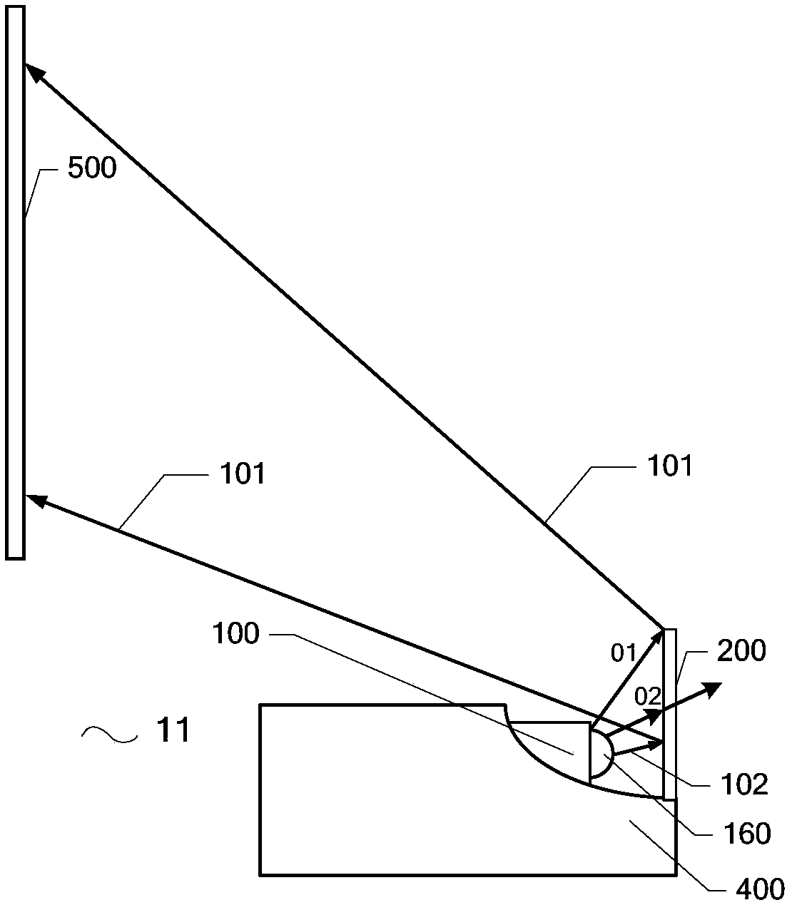
[0036] This embodiment provides a projection device, which is a reflective projection device 11 . Such as figure 2 As shown, the projection device includes an image source 100 and a transflective element 200 .

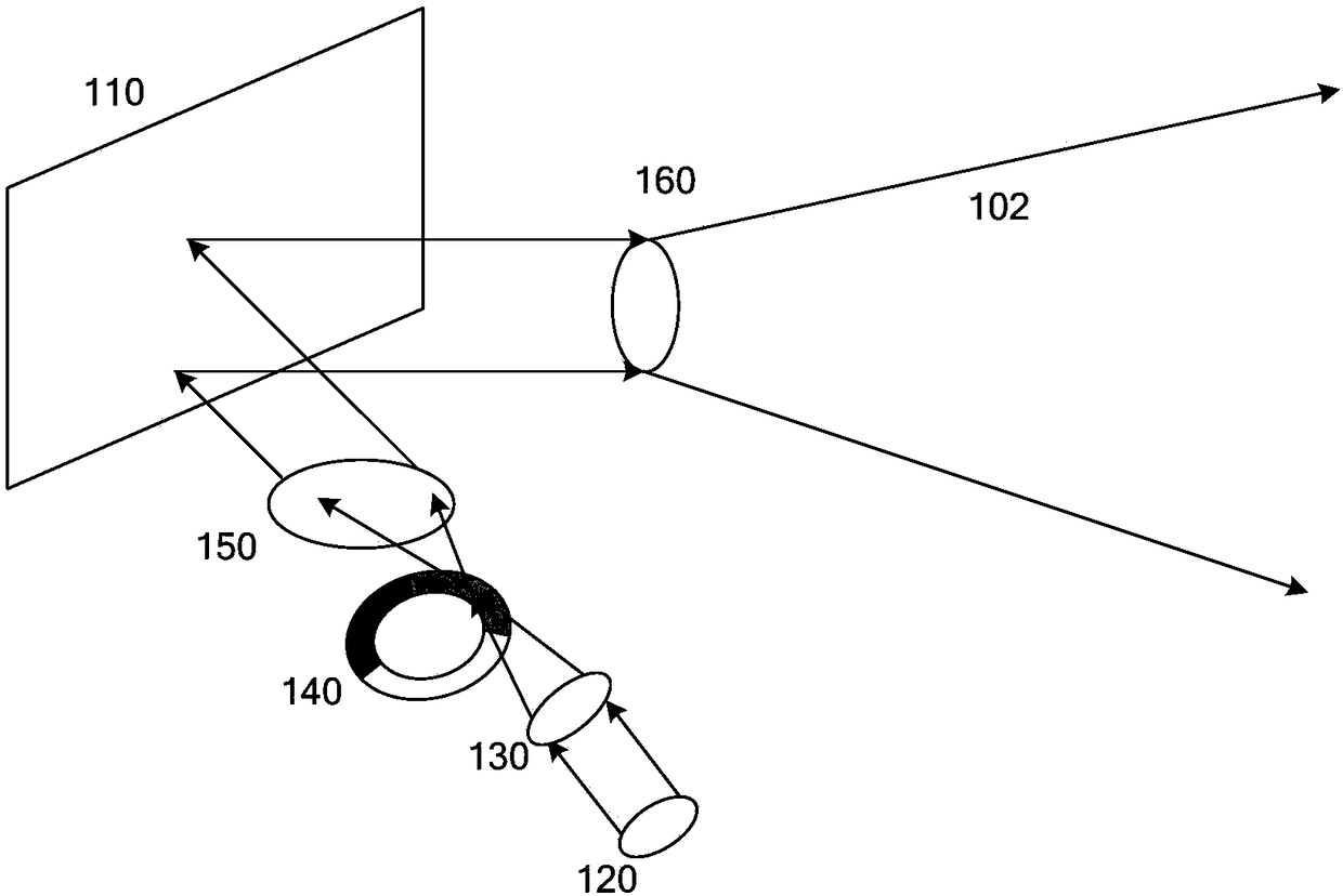
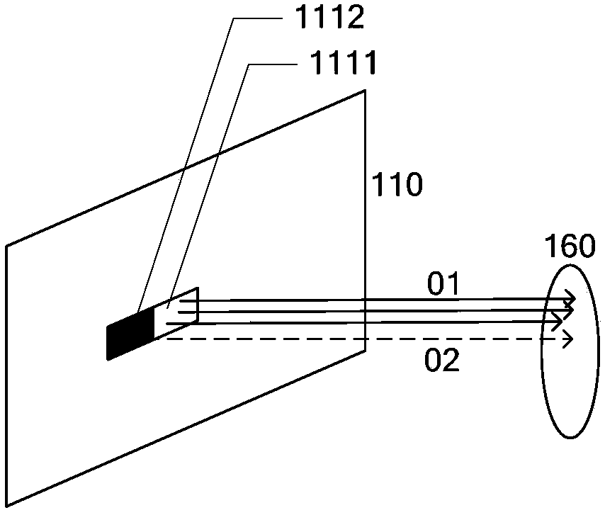
[0037] For example, if figure 2 As shown, image source 100 is configured to generate image light 102 and emit image light 102, image light 102 may include bright state area image light 01 and dark state area image light 02 (also as Figure 1b shown). The transflective element 200 is disposed on the light output side of the image source 100 and is configured to reflect the image light 102 emitted from the image source 100 for image display. For example, if figure 2 As shown in the light path diagram of , the transflective element 200 is configured to reflect the image light 01 in the bright state region for projection display, and configured to transmit the image light 02 in the dark state region for no projection display.

[0038] The transflective element 200 ...

Embodiment 2

[0063] This embodiment provides a projection device, such as Figure 8 As shown, the difference from the first embodiment is that the projection device of this embodiment is a direct projection projection device 12 . In the direct projection projection device 12, the transflective unit in the transmissive state in the transflective element 200 is configured to transmit the image light irradiated thereon for transmissive projection display, and the transflective unit in the reflective state in the transflective element 200 configured to reflect image light impinging on it. That is, the transflective unit is configured to reflect image light irradiated thereon when in a reflective state, or the transflective unit is configured to transmit image light irradiated thereon when in a transmissive state.

[0064] The transflective element 200 is configured to transmit the image light 102 emitted from the image source 100 for image display. For example, if Figure 8 As shown in the ...

Embodiment 3

[0076] This embodiment provides a method for driving a projection device, including:

[0077] Driving multiple pixels of the display unit so that each pixel is in an on state or in an off state;

[0078] Driving multiple transflective units of the transflective element, so that each transflective unit is in a reflective state or a transmissive state;

[0079] Wherein, the multiple transflective units of the transflective element are arranged on the light-emitting optical paths of the multiple pixels of the display unit;

[0080] When the driving pixel is in the off state, driving the transflective unit corresponding to the pixel is in the transmissive state; or,

[0081] When the driving pixel is in the off state, the transflective unit corresponding to the pixel is driven in the reflective state.

[0082]For example, the multiple transflective units of the transflective element are in one-to-one correspondence with the multiple pixels of the display unit.


PUM


Abstract

Provided are a projection device and a driving method thereof. The projection device includes an image source and a transflective element. The image source is configured to generate and emit image light, the image light including bright state area image light and dark state area image light. The transflective element includes a plurality of transflective units, and the transflective units have a reflective state and a transmissive state. The transflective unit is configured to reflect image light irradiated thereon when in a reflective state, or configured to transmit image light irradiated thereon when in a transmissive state. The transflective element is arranged on the light-emitting side of the image source, configured to transmit or reflect one of the image light in the bright state area for projection display, and configured to transmit or reflect the image light in the dark state area to make the other It does not project a display. The projection device can solve the problem of impurity in the black picture caused by the light leakage of the display unit, improve the contrast of the whole picture, and improve the picture display effect.

Description

technical field [0001] At least one embodiment of the present disclosure relates to a projection device and a driving method thereof. Background technique [0002] A projection device is a display device that magnifies tiny image information through a lens and images it on a screen. It is widely used in people's daily life, such as teaching, business, media advertising, home entertainment, etc. Projection devices can be divided into direct projection projection devices and reflective projection devices. The direct projection type projection device is that the projected light is directly projected onto the screen after being transmitted from the magnifying element. The reflective projection device is to place a reflector in front of the projection lens to reflect the projection light transmitted from the projection lens, and the projection light is projected onto the screen after reflection. In recent years, reflective projection devices using ultra-short focal length proje...

Claims


Application Information

Patent Timeline
Patent Type & Authority Patents(China)
IPC IPC(8): G03B21/14G03B21/28
CPCG03B21/142G03B21/28G03B21/005H04N9/3126H04N9/3114H04N9/3182H04N9/3155H04N5/7441H04N2005/745H04N9/317G03B21/006G03B21/008
Inventor 李召
Owner HEFEI BOE OPTOELECTRONICS TECH
Why Eureka
Try Eureka