
Linear optimal power flow model containing unified power flow controller

A technology of power flow controller and optimal power flow, which is applied to AC network circuits, AC networks with the same frequency from different sources, electrical components, etc., and can solve the problems of poor real-time performance and applicability

Active Publication Date: 2017-05-17
STATE GRID JIANGSU ELECTRIC POWER CO ELECTRIC POWER RES INST +2
View PDF4 Cites 23 Cited by
  • Summary
  • Abstract
  • Description
  • Claims
  • Application Information

AI Technical Summary

Problems solved by technology

[0005] The technical problem to be solved by the present invention is to provide a linearized optimal power flow model with a unified power flow controller for the situation that the AC optimal power flow with a unified power flow controller has poor real-time performance and applicability in the field of power system optimization dispatching

Method used


Image

  • Linear optimal power flow model containing unified power flow controller
  • Linear optimal power flow model containing unified power flow controller
  • Linear optimal power flow model containing unified power flow controller

Examples


Embodiment Construction

[0040] OPF is a typical nonlinear programming problem, and its nonlinearity is mainly reflected in the node power balance equation in the equality constraint.

[0041]

[0042] Where: P Gi ,P Di is the active power supply and active load of node i; Q Gi , Q Di is the reactive power supply and reactive load of node i; V i is the voltage amplitude of node i; G ij , B ij is the i-th row and j-th column element of the node admittance matrix; θ ij = θ i -θ j is the phase angle θ at both ends of the line i , θ j The phase angle difference; N is the number of nodes in the system.

[0043] 1. New LOPF model

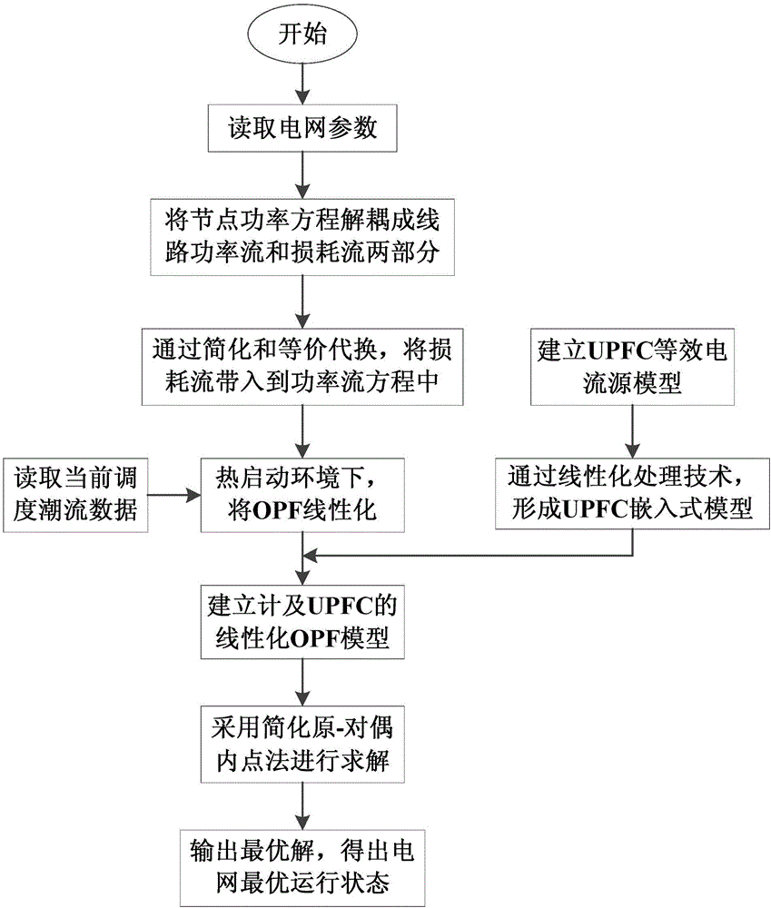
[0044] The present invention linearizes formula (1) mainly through three links of power flow decoupling, equivalent substitution and hot start environment linearization.

[0045] 1) Power flow decoupling: firstly, the line power flow in formula (1) is decoupled into two parts: line power flow and line loss

[0046]

[0047] Where: P il , Qil is the active and ...


PUM


Abstract

The invention discloses a linear optimal power flow (LOPF) model containing a unified power flow controller (UPFC). DC optimal power flow (DCOPF) is the most popular OPF linear method so far, and is fast in solution speed but relatively low in calculation accuracy, and two electrical quantities of a node voltage amplitude value and a circuit reactive power cannot be solved; the UPFC can be used for improving the power supply capability of a regional power grid, the UPFC is introduced into a DCOPF model, thus, the problem complexity is improved, and the linear DCOPF is also converted to a non-linear model; on the basis, the invention proposes a novel LOPF model which is higher in accuracy and is more perfect; by the model, the voltage and the reactive power can be solved, a current source type steady-state model of the UPFC is processed and is equivalently embedded into a circuit, and thus, the novel LOPF model is applicable to the LOPF model proposed by the invention; and an example simulation result shows that the high efficiency of the linear model is maintained, the calculation result has relatively high accuracy, and moreover, power flow information which is more perfect than the DCOPF model can be figured out.

Description

technical field [0001] The invention relates to a linearized optimal power flow model including a unified power flow controller, which belongs to the field of power system optimization operation. Background technique [0002] Unified power flow controller (UPFC), as the third generation of Flexible AC Transmission System (FACTS), integrates a variety of flexible control methods of FACTS components, and can control node voltage, phase angle and line Impedance can quickly and flexibly control and adjust the active and reactive power flow of the line without changing the existing grid structure, and reasonably distribute the system flow, thereby improving the power supply capacity of the regional power grid. In addition, UPFC also plays a positive role in limiting short-circuit current and reducing system network loss. [0003] The optimal power flow (OPF) of the power system can realize the optimal stable operation state of the predetermined target by adjusting the available ...

Claims


Application Information

Patent Timeline
IPC IPC(8): H02J3/00H02J3/06
CPCH02J3/00H02J3/06H02J2203/20
Inventor 刘建坤陈静李群卫志农孙国强臧海祥何天雨
Owner STATE GRID JIANGSU ELECTRIC POWER CO ELECTRIC POWER RES INST
Learn More