High frequency power amplifier, transmitter and mobile communication terminal using the power amplifier

a technology of power amplifier and high frequency, which is applied in the direction of low noise amplifier, gain control, transmission, etc., can solve the problems of high cost of isolators and system distortion, and achieve excellent linearity and easy downsizing

Active Publication Date: 2006-11-30
RENESAS ELECTRONICS CORP
View PDF30 Cites 53 Cited by
  • Summary
  • Abstract
  • Description
  • Claims
  • Application Information

AI Technical Summary

Benefits of technology

[0011] The present invention has been made to solve the above problem, and therefore an object of the present invention is to provide a high frequency power amplifier that maintains an excellent linearity regardless of a fluctuation of the load impedance and is readily downsized, and a transmitter using the power amplifier.
[0014] According to the present invention, there can be provided a high frequency power amplifier that maintains an excellent linearity regardless of a fluctuation of the load impedance, and a transmitter using the power amplifier.

Problems solved by technology

Now, in a CDMA system that is required that the power amplifier operates as a linear amplifier, the characteristic indicated by the characteristic (1) of FIG. 1 saturates the output at a lower output than the original linear maximum output, resulting in such a problem that a distortion that exceeds a permissible value of the system may occur.
However, there arises such a problem that the isolator is expensive, and the power amplifier is not downsized.

Method used


Image

  • High frequency power amplifier, transmitter and mobile communication terminal using the power amplifier
  • High frequency power amplifier, transmitter and mobile communication terminal using the power amplifier
  • High frequency power amplifier, transmitter and mobile communication terminal using the power amplifier

Examples


first embodiment

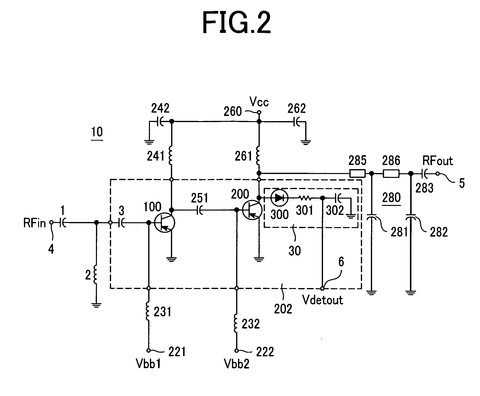
[0034] First, a description will be given of a structure of a high frequency power amplifier according to a first embodiment of the present invention with reference to FIG. 2. FIG. 2 is a circuit diagram showing a high frequency power amplifier 10 according to the first embodiment of the present invention.

[0035] According to the first embodiment of the present invention, the high frequency power amplifier 10 detects an AC voltage amplitude at an output terminal of a final amplification stage transistor, and outputs a signal for suppressing an input signal amplitude of the power amplifier when the detected voltage amplitude exceeds a predetermined specified value.

[0036] In other words, in the high frequency power amplifier 10 shown in FIG. 2, reference numeral 1 and 3 denote input matching capacitors of the amplifier, and 2 is an input matching inductor. Reference numeral 100 denotes an initial stage amplification transistor, 200 is a final stage amplification transistor, and 30 is...

second embodiment

[0043] A description will be given of an example of a transmitter using the power amplifier of the first embodiment according to a second embodiment of the present invention with reference to FIGS. 3 to 5C.

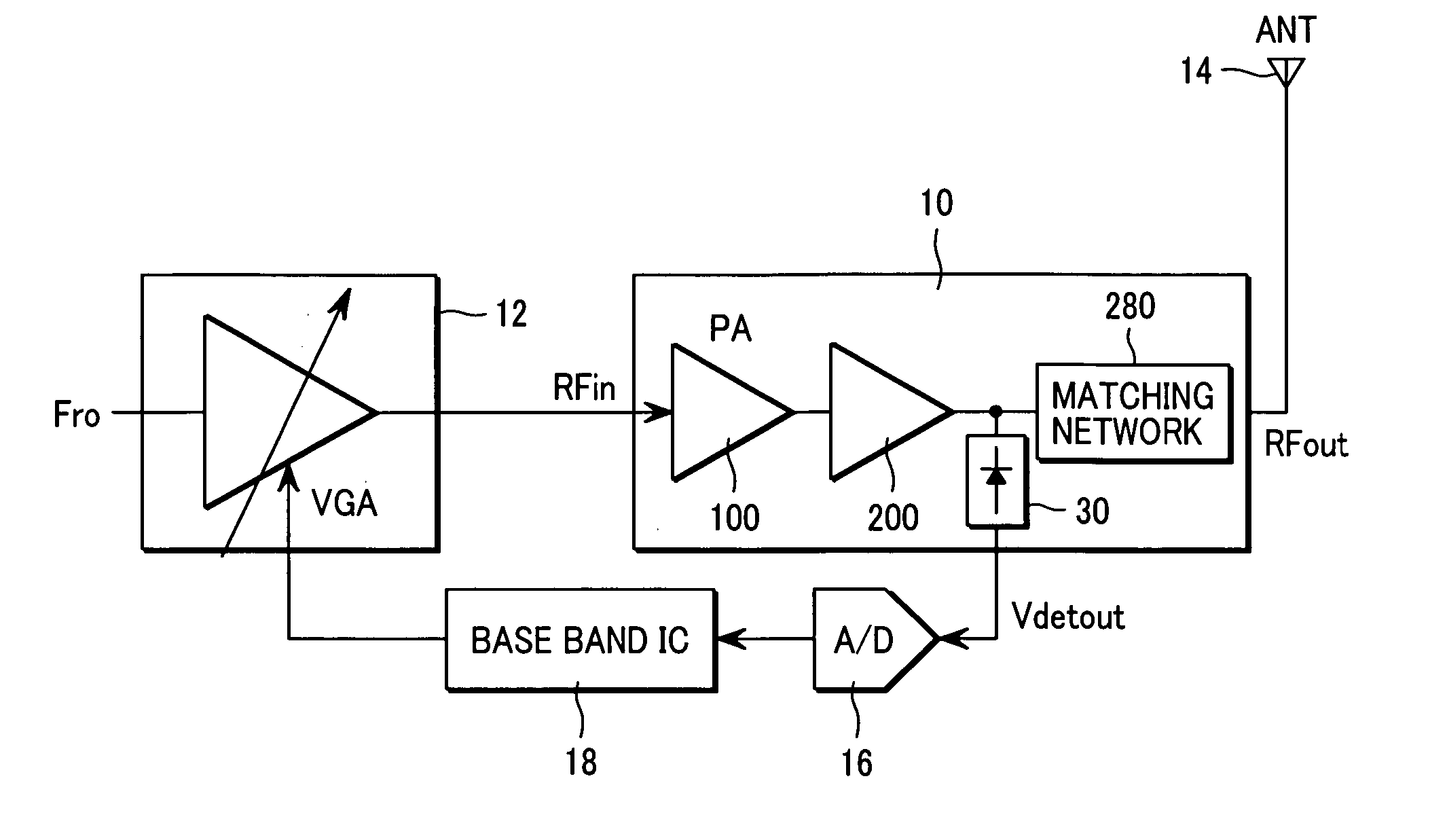
[0044] First, FIG. 3 is a block diagram showing a structural example of a transmitter to which the power amplifier shown in FIG. 2 is applied. The power amplifier 10 has an RF input signal RFin terminal 4 connected to an external gain variable amplifier 12, and has an RF output signal RFout terminal 5 connected to an antenna 14. Also, the power amplifier 10 has a terminal 6 that outputs an AC voltage amplitude output Vdetout of the collector AC voltage detector unit 30 in the power amplifier 10 connected to a control circuit 18 through an A / D converter 16. The control circuit 18 is disposed within the transmitter, more preferably within a base band control circuit (base band IC).

[0045] A high frequency transmit signal Fr0 obtained by modulating a carrier wave in phase on the bas...

third embodiment

[0063] A third embodiment of the present invention will be described with reference to FIGS. 6A and 6B. In this embodiment, the high frequency power amplifier shown in FIG. 2 or 3 is applied to a mobile communication terminal of the W-CDMA system.

[0064] A mobile communication terminal shown in FIG. 6A includes a high frequency signal processor circuit that has a modulator and demodulator circuit which is capable of modulating and demodulating the W-CDMA signal, and is brought into a semiconductor integrated circuit. That is, the mobile communication terminal includes an electronic device 600, a high frequency power amplifier (power module) 700, and a front end module 800.

[0065] In the electronic device 600 corresponding to the base band control circuit (base band IC) shown in FIG. 3, a modulator and demodulator circuit which is capable of modulating and demodulating the W-CDMA signal, and a base band circuit 610 that generates I and Q signals or processes the I and Q signals that ...


PUM


Abstract

A high frequency power amplifier maintains an excellent linearity regardless of a fluctuation of a load impedance and is downsized. The high frequency power amplifier detects an AC voltage amplitude at an output terminal of a final amplification stage transistor, and suppresses an input signal amplitude of a power amplifier when the voltage amplitude exceeds a predetermined threshold value.

Description

CLAIM OF PRIORITY [0001] The present application claims priority from Japanese application JP 2005-138142 filed on May 11, 2005, the content of which is hereby incorporated by reference into this application. FIELD OF THE INVENTION [0002] The present invention relates to a high frequency power amplifier used in a high frequency mobile communication terminal and a transmitter using the power amplifier, and more particularly to a high frequency power amplifier that reduces a load impedance dependency of the amplifier characteristic, and a transmitter using the power amplifier. BACKGROUND OF THE INVENTION [0003] Japanese Patent Laid-Open No. 2000-341143 discloses an example of a structure of a conventional amplifier that reduces a dependency of the characteristic on a load impedance. The amplifier disclosed in Japanese Patent Laid-Open No. 2000-341143 conducts detection at plural points on a transmission line between a power amplifier and an antenna, detects the occurrence of a standin...

Claims


Application Information

Patent Timeline
Patent Type & Authority Applications(United States)
IPC IPC(8): H03G3/00
CPCH03F1/0261H03F3/191H03F3/24H03F2200/105H03G3/3042H03F2200/294H03F2200/372H03F2200/471H03F2200/99H03F2200/207
Inventor TANOUE, TOMONORIMATSUMOTO, HIDETOSHI
Owner RENESAS ELECTRONICS CORP
Why Eureka
Try Eureka