Field weakening control method for built-in permanent magnet synchronous motor

A permanent magnet synchronous motor and field weakening control technology, applied in motor generator control, electronic commutation motor control, control system and other directions, can solve problems such as stability decline, difficult design, system instability, etc., to improve stability , easy to design effects

Active Publication Date: 2014-04-02
WISDRI WUHAN AUTOMATION
View PDF4 Cites 52 Cited by
  • Summary
  • Abstract
  • Description
  • Claims
  • Application Information

AI Technical Summary

Problems solved by technology

Therefore, the stability of this method decreases with the speed, and the proportional-integral (PI) controller parameters of the output voltage vector amplitude control are very difficult to design due to the constraints of the two aspects mentioned above. The controller can be designed as an integral type (I), if a proportional (P) is added, the system is likely to be unstable

Method used


Image

  • Field weakening control method for built-in permanent magnet synchronous motor
  • Field weakening control method for built-in permanent magnet synchronous motor
  • Field weakening control method for built-in permanent magnet synchronous motor

Examples


Embodiment Construction

[0024] The present invention will be further described below in conjunction with specific examples and accompanying drawings.

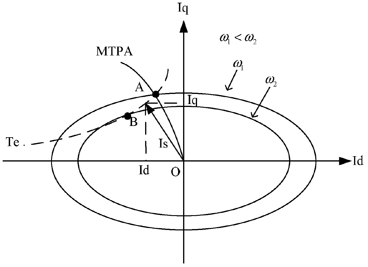
[0025] When the built-in permanent magnet synchronous motor operates in the medium and high speed range, the voltage drop generated by the motor stator resistance accounts for a negligible proportion in the stator voltage. At this time, the steady-state voltage equation of the motor can be described by Equation 1.

[0026] u d =-ωL q i q

[0027] u q =ω(L d i d +ψ f ) (1),

[0028] where u d , u q is the d-axis and q-axis motor stator voltage, ω is the electrical angular velocity of the motor, L d , L q is the d-axis and q-axis excitation inductance of the motor, ψ f is the flux linkage of the permanent magnet rotor.

[0029] Since the maximum output voltage of the motor controller is limited by the bus voltage, formula 2 must be satisfied.

[0030] u d 2 + u...


PUM


Abstract

The invention provides a field weakening control method for a built-in permanent magnet synchronous motor. The method comprises the following steps: motor speed closed-loop control in a field non-weakening region: the output of a speed loop is the current directive value i<*>q of an axis q, the current directive value i<*>d of an axis d is calculated from i<*>q according to an MTPA relation, and i<*>d, i<*>q and the actual feedback values id and iq thereof are subjected to closed-loop control to output the voltage directive values of the axis d and the axis q; difference value amplitude-limiting processing: whether to enter a field weakening region is judged, if yes, an output voltage amplitude value controls a PI (Proportional-Integral) controller to work and controls a PI adjustor to perform difference value amplitude-limiting processing and output Deltaiq, otherwise, the output voltage amplitude value controls the PI controller not to work, and the output is 0; in case of entering the field weakening region, the output i<*>q of the speed loop is only used as the current directive value of the axis d after MTPA calculation, and the sum of the output of the front beat of the speed loop before entering the field weakening region and Deltaiq serves as the current directive value of the axis q in the field weakening region.

Description

technical field [0001] The invention belongs to the field of built-in permanent magnet synchronous motors, and is specifically applied to the field-weakening control of built-in permanent magnet synchronous motors requiring a large speed regulation range. Background technique [0002] The permanent magnet synchronous motor replaces the DC field winding of the wound synchronous motor with permanent magnets. Its advantage is that compared with the asynchronous motor, there is no copper loss of the excitation winding, and it has a high power density, so the motor has high efficiency, the inertia of the rotor is small, and the structural strength of the rotor is also high. Due to the above advantages, now small and medium power electric vehicles generally choose permanent magnet synchronous motors as the traction motors of the vehicles. [0003] There are two types of permanent magnet synchronous motors: surface-mounted and built-in. The permanent magnets of the surface-mounte...

Claims


Application Information

Patent Timeline
Patent Type & Authority Applications(China)
IPC IPC(8): H02P21/00
Inventor 余骏王国强康现伟卢家斌
Owner WISDRI WUHAN AUTOMATION
Why Eureka
Try Eureka