Scraping structure for rollers

A technology of scraper and scraper frame, which is applied in the field of roller scraper structure, can solve the problems of poor scraper effect and scraper wear, and achieve the effect of simple structure

Active Publication Date: 2017-05-24
CHONGQING ZHOUYI FOOD CO LTD
View PDF9 Cites 7 Cited by
  • Summary
  • Abstract
  • Description
  • Claims
  • Application Information

AI Technical Summary

Problems solved by technology

[0004] Due to the strong viscosity of the dough, the surface of the roll is easy to stick to the surface during the pressing process of the roll. In the prior art, a scraper that is usually fixed against the surface of the roll is usually fixed on the noodle press, so that the sticking on the surface of the roll Scraping on the surface, because the scraper and the surface of the roller rub against each other during use, the scraper is prone to wear, which will lead to poor scraping effect

Method used


Image

  • Scraping structure for rollers
  • Scraping structure for rollers
  • Scraping structure for rollers

Examples


Embodiment 1

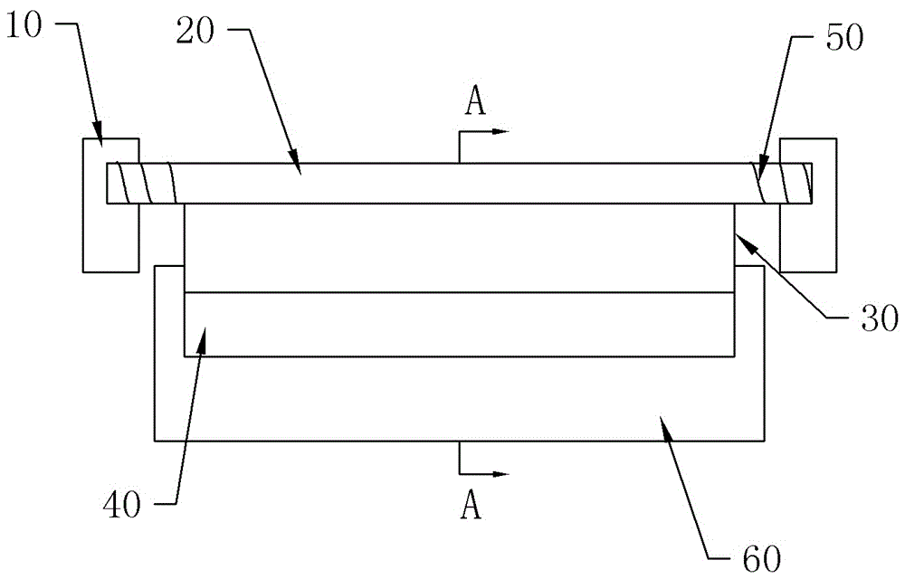
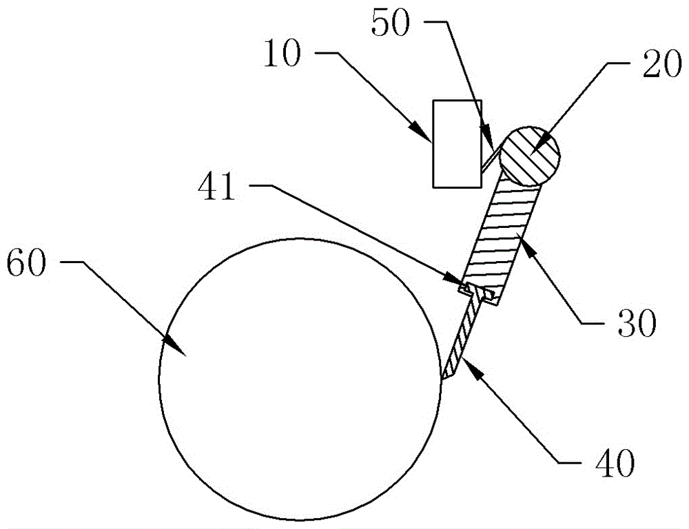
[0025] Embodiment 1 is basically as attached figure 1 and figure 2 Shown: a scraping structure for roll 60, including installation frame 10, rotating shaft 20, scraper holder 30, scraper 40 and elastic member for resetting the rotating shaft 20, in this embodiment, the elastic member used is torsion spring 50 , Two torsion springs 50 are installed on the rotating shaft 20 . The torsion spring 50 can provide the rotating force of the rotating shaft 20 , and make the rotating shaft 20 drive the scraper holder 30 and the scraper 40 , so that the scraper 40 abuts against the surface of the roll 60 . The structure that the torsion spring 50 resets as an elastic member is simple. The rotating shaft 20 is rotatably connected to the mounting frame 10 , the scraper frame 30 is mounted on the rotating shaft 20 , the scraper 40 is detachably connected to the scraper frame 30 , and under the reset action of the torsion spring 50 , the scraper 40 is offset against the surface of the rol...

Embodiment 2

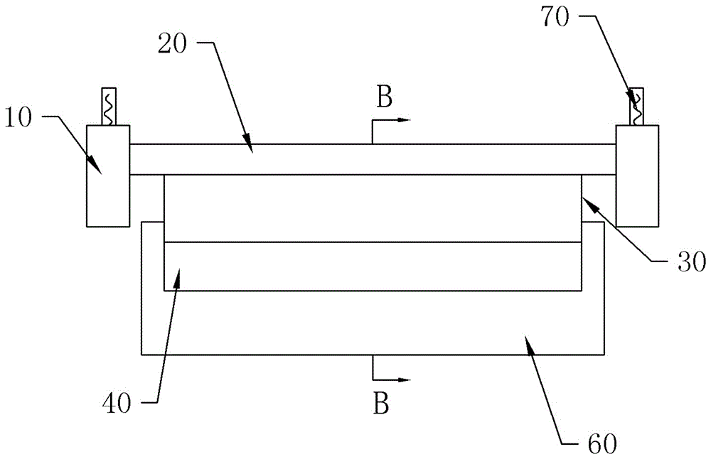
[0028] like image 3 and Figure 4 As shown, the difference with Embodiment 1 is that the elastic member in this embodiment adopts a tension spring 70, and the rotating shaft 20 is threadedly connected with a pole arranged in the radial direction, and one end of the tension spring 70 is connected with the pole, and the other end Connect with the mounting frame 10. During use, the extension spring 70 exerts force on the support rod, so that the rotating shaft 20 rotates, and the rotating shaft 20 drives the scraper holder 30 and the scraper 40 to rotate, and the scraper 40 is against the surface of the roll 60 . The extension spring 70 has a good elastic coefficient and has a long service life.

Embodiment 3

[0030] like Figure 5 As shown, the difference with Embodiment 2 is that: both sides of the scraper 40 are embedded with electromagnets 80, and the corresponding positions on the roll 60 are embedded with magnetic parts that attract each other with the two electromagnets 80. The magnetic parts are permanent magnets. During specific use, the electromagnet 80 is energized, and the electromagnet 80 on the scraper 40 is then attracted to the permanent magnet on the roll 60, so that the scraper 40 can be offset against the surface of the roll 60 to play an auxiliary role; Size is controllable, so just can control the force that scraper 40 and roll 60 surface resist, if the viscous force of dough and roll 60 is bigger, then control increases the magnetic force of electromagnet 80; If the viscous force of dough and roll 60 is less, Then the magnetic force of the electromagnet 80 is controlled to be reduced to reduce wear.


PUM


Abstract

The invention discloses a scraping structure for rollers. The scraping structure comprises a mounting rack, a rotating shaft, a scraper holder, a scraper and an elastic part for restoring the rotating shaft, wherein the rotating shaft is in rotating connection on the mounting rack; the scraper holder is arranged on the rotating shaft; the scraper is detachably connected with the scraper holder; and the scraper is butted against a roller surface under the restoring effect of the elastic part. According to the scraping structure, the scraper is always in contact with rollers, and thus the scraping effect is ensured.

Description

technical field [0001] The invention belongs to the field of noodle presses, and in particular relates to a scraping structure for rollers. Background technique [0002] The noodle press machine is a food machine that mixes flour and water evenly and replaces traditional manual kneading. It can be used to make noodles, swallow skins, cakes, pastries, etc. The noodles and gluten pressed by the noodle press machine have high toughness, cooking resistance and breaking resistance. It is suitable for family hotels, restaurant canteens, pastry factories, inkstones, bakeries and various It is used by pastry processing units or individual industrial and commercial households. [0003] Industrial large and medium-sized noodle presses, also known as tablet presses, are used to roll the dough from thick to thin into dough sheets through multiple rollers that rotate relatively through the dough that has been kneaded and matured. Sheeting is an important step in the production of dried...

Claims


Application Information

Patent Timeline
Patent Type & Authority Applications(China)
IPC IPC(8): A21C3/02
CPCA21C3/02
Inventor 周长义
Owner CHONGQING ZHOUYI FOOD CO LTD
Why Eureka
Try Eureka