
Multifunctional colloidal sol stirring device

A stirring device and a multi-functional technology, applied in the field of multi-functional sol stirring devices, can solve the problems of rapid damage of the rotating shaft, inconvenient feeding, uneven stirring, etc., and achieve the effects of improving the sol effect, convenient feeding and prolonging the service life.

Pending Publication Date: 2017-05-24
天津中鼎生物医学科技有限公司
View PDF0 Cites 1 Cited by
  • Summary
  • Abstract
  • Description
  • Claims
  • Application Information

AI Technical Summary

Problems solved by technology

The stirring paddle of the current sol tank extends vertically from the upper part of the tank to the bottom of the tank. Such a structural design requires a long shaft, which causes the defects of quick damage to the shaft, inconvenient feeding, and uneven stirring.

Method used


Image

  • Multifunctional colloidal sol stirring device
  • Multifunctional colloidal sol stirring device
  • Multifunctional colloidal sol stirring device

Examples


Embodiment 1

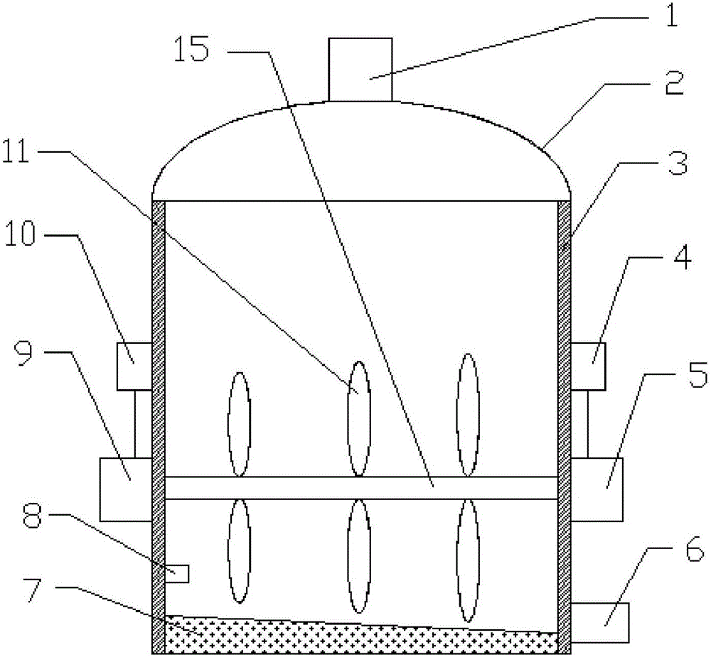
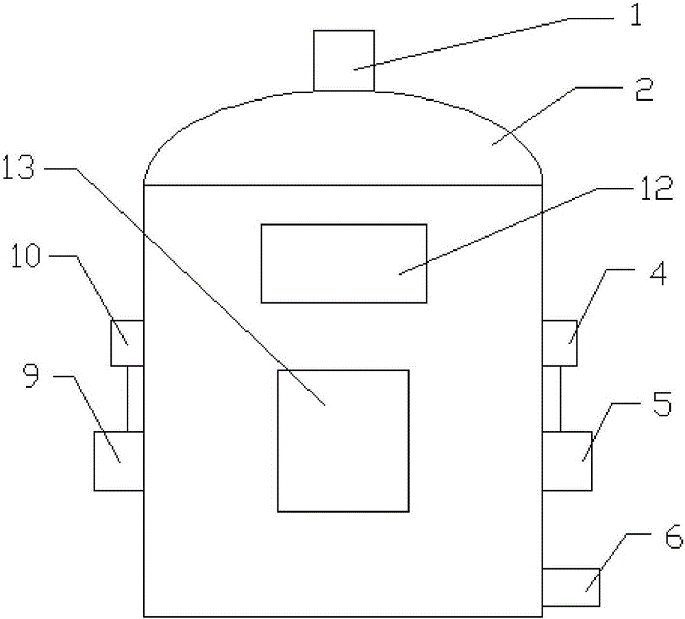
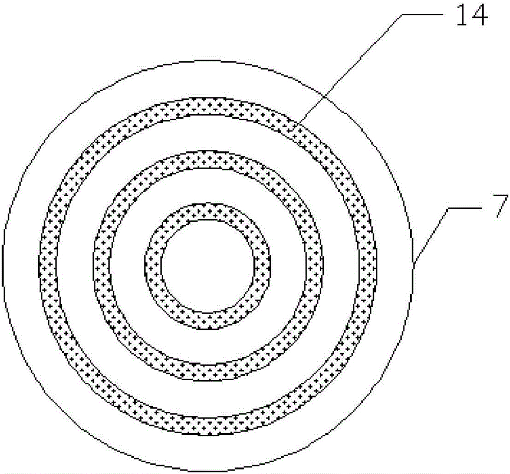
[0020] A multifunctional sol stirring device, comprising a feed inlet 1, a tank body 2, an insulation layer 3, a first motor 4, a first governor 5, a discharge outlet 6, a heating layer 7, a temperature sensor 8, a second regulator Speed ​​9, second motor 10, stirring paddle 11, viewing window 12, controller 13 and annular heater 14, the top center of tank body 2 is fixedly installed feed inlet 1, is also provided with viewing window 12 on tank body 2 And controller 13, two groups of motors and speed governors are respectively the first motor 4 and the first speed governor 5, the second motor 10 and the second speed governor 9, and the motors and speed governors of the two groups are respectively installed in On both sides of the tank body 2, the first speed governor 5 and the second speed governor 9 are respectively connected to the two ends of the stirring shaft 15, the first motor 4 is electrically connected to the first speed governor 5, and the second motor 10 is connected...

Embodiment 2

[0026] A multifunctional sol stirring device, comprising a feed inlet 1, a tank body 2, an insulation layer 3, a first motor 4, a first governor 5, a discharge outlet 6, a heating layer 7, a temperature sensor 8, a second regulator Speed ​​9, second motor 10, stirring paddle 11, viewing window 12, controller 13 and annular heater 14, the top center of tank body 2 is fixedly installed feed inlet 1, is also provided with viewing window 12 on tank body 2 And controller 13, two groups of motors and speed governors are respectively the first motor 4 and the first speed governor 5, the second motor 10 and the second speed governor 9, and the motors and speed governors of the two groups are respectively installed in On both sides of the tank body 2, the first speed governor 5 and the second speed governor 9 are respectively connected to the two ends of the stirring shaft 15, the first motor 4 is electrically connected to the first speed governor 5, and the second motor 10 is connected...


PUM


Abstract

The invention discloses a multifunctional colloidal soil stirring device. The multifunctional colloidal soil stirring device comprises a tank body (2), wherein a feeding port (1) is fixedly mounted at the center of the top of the tank body (2); a window (12) and a controller (13) are further arranged on the tank body (2); one of two motor and speed regulator groups comprises a first motor (4) and a first speed regulator (5), and the other of the two motor and speed regulator groups comprises a second motor (10) and a second speed regulator (9); the first speed regulator (5) and the second speed regulator (9) are connected with two ends of a stirring rotating shaft (15) respectively; the motors and the corresponding speed regulators are electrically connected; stirring blades (11) are mounted on the stirring rotating shaft (15); a heating layer (7) is arranged at the bottom of the tank body (2); an annular heater (14) is arranged in the heating layer (7); an insulating layer (3) is arranged on the inner wall of the tank body (2); a temperature sensor (8) is arranged in the position, close to the bottom of the tank body (2), of the insulating layer (3). The stirring blades are arranged on the side surface of the colloidal sol tank body, so that the colloidal sol effect is improved.

Description

technical field [0001] The invention relates to the technical field of stirring equipment, in particular to a multifunctional sol stirring device. Background technique [0002] The hollow capsule is composed of a capsule shell with a cap and a body refined from medicinal gelatin and auxiliary materials. Mainly used to contain solid medicine. For example, self-made powders, health care products, medicines, etc., have solved the problems of difficulty in mouthfeeling and poor taste for users, and truly realized that good medicine is no longer bitter. Hollow capsules are becoming more and more popular. First of all, capsules are slender in shape and easy to swallow, making them the most popular dosage form for consumers. In addition, capsules can effectively cover up the unpleasant taste and smell of the contents. The stirring paddle of the current sol tank extends vertically from the top of the tank to the bottom of the tank. Such a structural design requires a long shaft, w...

Claims


Application Information

Patent Timeline
Patent Type & Authority Applications(China)
IPC IPC(8): B01F7/04B01F15/06
CPCB01F27/70B01F35/2115B01F35/221422B01F35/3215B01F35/51B01F35/3204B01F35/93B01F2035/99B01F2101/22
Inventor 赵君鸿孙秀春王路王冠华王欣怡
Owner 天津中鼎生物医学科技有限公司
Learn More