Non-rotating metal spinning experiment platform

A metal spinning, experimental platform technology, applied in metal processing, metal processing equipment, manufacturing tools, etc., can solve problems such as difficult to process non-rotating parts

Inactive Publication Date: 2017-05-24
SHANDONG UNIV OF SCI & TECH
View PDF6 Cites 1 Cited by
  • Summary
  • Abstract
  • Description
  • Claims
  • Application Information

AI Technical Summary

Problems solved by technology

[0003] The present invention provides a non-rotating body metal spinning experimental platform in order to solve the defect

Method used


Image

  • Non-rotating metal spinning experiment platform

Examples


Embodiment Construction

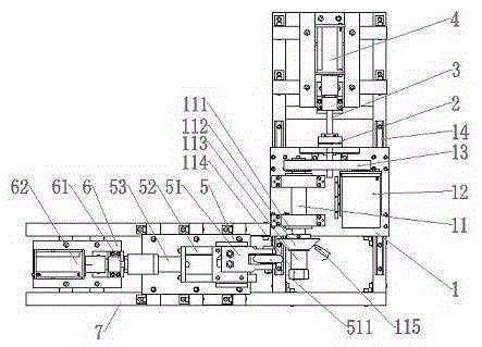
[0013] Such as figure 1 As shown, the non-revolving metal spinning experimental platform disclosed by the present invention includes a fuselage, a movable worktable (1) installed on the fuselage; a main shaft (11) and a drive main shaft ( 11) Rotating stepping motor (12), the two are placed in parallel, and the stepping motor (12) drives the main shaft (11) to rotate through the synchronous belt (13); there is a driving main shaft (11) behind the movable worktable (1) ) servo motor (4) for axial feeding, the servo motor (4) drives the movable worktable (1) along the Feed in Z axis direction.

[0014] The main shaft (11) is provided with a positioning ring (111) for fixing the ceramic mandrel (112), and the end of the main shaft is threaded. Cylinder clamping block (113) to withstand the billet, and then screw in the clamping nut (114) to tighten the jacking block to prevent the billet from shifting and falling during the rotation of the mandrel (112); the billet is fixed Af...


PUM


Abstract

The invention relates to a non-rotating metal spinning experiment platform which comprises a machine body and a movable workbench installed on the machine body. The movable workbench is provided with a main shaft and a stepping motor for driving the main shaft to rotate. A servo motor for driving the main shaft to achieve axial feed is arranged behind the movable workbench. A blank self-blocking heating device is arranged on one side in the front of the main shaft, and the blank self-blocking heating device makes contact with a blank all the time through a leaf spring with a metal roller in the heating process. The other side in the front of the main shaft is provided with a spinning wheel feeding device. The spinning wheel feeding device is provided with an angle-adjustable spinning wheel frame and a servo motor for driving the spinning wheel to achieve feed. The stepping motor and the servo motor are both connected with a numerical control device which coordinates work of all the mechanisms. According to the non-rotating metal spinning experiment platform, by means of control over the feeding movement of the spinning wheel and the main shaft, spinning machining for non-rotating metal parts can be achieved.

Description

technical field [0001] The invention relates to a spinning experimental platform capable of processing non-revolving metal workpieces. Background technique [0002] The spinning process is a relatively advanced metal forming process. During the rotation of the blank with the die or the rotation of the spinning tool around the blank, the spinning tool is fed against the blank so that the blank is compressed and subjected to continuous, point-by-point deformation. Due to the simplicity of equipment and molds, the application of spinning technology has become very common. However, due to the limitation of the movement mode of the spinning process, the application of the spinning process is generally only for the processing of some rotating metal parts. Contents of the invention [0003] In order to solve the defect that the spinning machine in the prior art can only spin rotating parts and it is difficult to process non-rotating parts, the invention provides a non-rotating ...

Claims


Application Information

Patent Timeline
IPC IPC(8): B21D22/16B21C51/00
CPCB21D22/16B21C51/00
Inventor 刘杰李震秦升学袁腾
Owner SHANDONG UNIV OF SCI & TECH
Why Eureka
Try Eureka