Optical fiber preform rod polishing solution circulating system

A technology of optical fiber preform and circulation system, which is applied in the direction of grinding/polishing equipment, manufacturing tools, metal processing equipment, etc. It can solve the problems of optical fiber preform mechanical properties (high brittleness, easy to scratch the surface, etc.) and achieve high integration , Easy operation and installation, simple structure

Inactive Publication Date: 2017-05-24
UNIV FOR SCI & TECH ZHENGZHOU
View PDF8 Cites 5 Cited by
  • Summary
  • Abstract
  • Description
  • Claims
  • Application Information

AI Technical Summary

Problems solved by technology

Restricted by the mechanical properties of the optical fiber preform (high brittleness, easy to scratch the surface, etc.), shape (inner and outer cylindrical surfaces), size (length: 150mm, diameter: 20mm, inner diameter: 3-8mm) and equipment investment, etc., making The choice of polishing method has great limitations

Method used


Image

  • Optical fiber preform rod polishing solution circulating system

Examples


Embodiment Construction

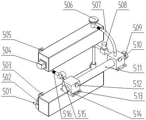
[0020] An optical fiber preform polishing liquid circulation system, the system includes an upper water tank 505, a lower water tank 503, a first conduit 501, a second conduit 516, a third conduit, an elbow 507, a first solenoid valve 502, and a second solenoid valve. Valve 508, left support seat 513, right support seat, water pump 515, agitator 504;

[0021] The upper water tank 505 is fixed on the chassis frame, and the lower water tank 503 is fixed on the chassis frame and located below the upper water tank 505;

[0022] The lower water outlet hole of the upper water tank 505 is connected to the water pump 515 through the second conduit 516, and then connected to the water inlet on the left support base 513;

[0023] The first water outlet on the right support seat is connected to the water inlet of the lower water tank 503 through the second solenoid valve 508 through the third conduit, and the second water outlet on the right support seat is connected to the water inlet o...


PUM


Abstract

The invention mainly relates to the field of optical fiber preform rod inner hole and external cylindrical surface polishing, in particular to an optical fiber preform rod polishing solution circulating system, which comprises an upper water tank, a lower water tank, a first guiding pipe, a second guiding pipe, a third guiding pipe, a bending pipe, a first solenoid valve, a second solenoid valve, a left support seat, a right support seat, a water pump and a stirrer. The optical fiber preform rod polishing solution circulating system provided by the invention is simple in structure, high in integration level, and convenient to operate and install, a polishing solution used by the circulating system can be repeatedly used, and an excircle and an inner hole of an optical fiber preform rod immersed in a polishing agent loop can be polished.

Description

technical field [0001] The invention mainly relates to the field of polishing the inner hole and the outer cylindrical surface of an optical fiber preform, in particular to an optical fiber preform polishing liquid circulation system. Background technique [0002] The core of optical fiber manufacturing is optical fiber preform manufacturing technology. At present, the common optical fiber processing methods mainly include deposition method (chemical vapor phase, vapor phase outside the tube, plasma vapor phase) and mechanical method. The current process is to first manufacture the preform mandrel, and then use different techniques to manufacture the outer cladding outside the mandrel. Compared with the deposition method, the mechanical method has less initial investment and is suitable for batch processing of special optical fibers. The main implementation process of the mechanical method is the preparation of the original optical fiber glass, the processing of the pref...

Claims


Application Information

Patent Timeline
Patent Type & Authority Applications(China)
IPC IPC(8): B24B57/02B24B1/00
CPCB24B57/02B24B1/005
Inventor 张玉华齐仁龙贾华坡石佩斐赵豪杰曹晓彦陈林林周凯凯
Owner UNIV FOR SCI & TECH ZHENGZHOU
Why Eureka
Try Eureka