Pneumatic component installing structure

A technology for installing structures and components, applied in gas/liquid distribution and storage, program control manipulators, manipulators, etc., can solve problems such as winding, knotting, affecting normal gas supply, etc., to avoid damage and smooth gas supply.

Active Publication Date: 2017-05-24
ZHUHAI GREE INTELLIGENT EQUIP CO LTD +1
View PDF3 Cites 1 Cited by
  • Summary
  • Abstract
  • Description
  • Claims
  • Application Information

AI Technical Summary

Problems solved by technology

As we all know, the sixth axis of an industrial robot can rotate at a large angle. The fixture installed on the sixth axis has an air supply pipe, and the phenomenon of knotting and winding will occur when rotating at a large angle, which will affect the normal air supply.

Method used


Image

  • Pneumatic component installing structure
  • Pneumatic component installing structure
  • Pneumatic component installing structure

Examples


Embodiment Construction

[0019] The present invention is described below based on examples, but the present invention is not limited to these examples. In the following detailed description of the invention, some specific details are set forth in detail. The present invention can be fully understood by those skilled in the art without the description of these detailed parts. To avoid obscuring the essence of the present invention, well-known methods, procedures, procedures, and components have not been described in detail.

[0020] Additionally, those of ordinary skill in the art will appreciate that the drawings provided herein are for illustrative purposes and are not necessarily drawn to scale.

[0021] Unless the context clearly requires, throughout the specification and claims, "comprises", "comprises" and similar words should be interpreted in an inclusive sense rather than an exclusive or exhaustive meaning; that is, "including but not limited to" meaning.

[0022] In the description of the ...


PUM


Abstract

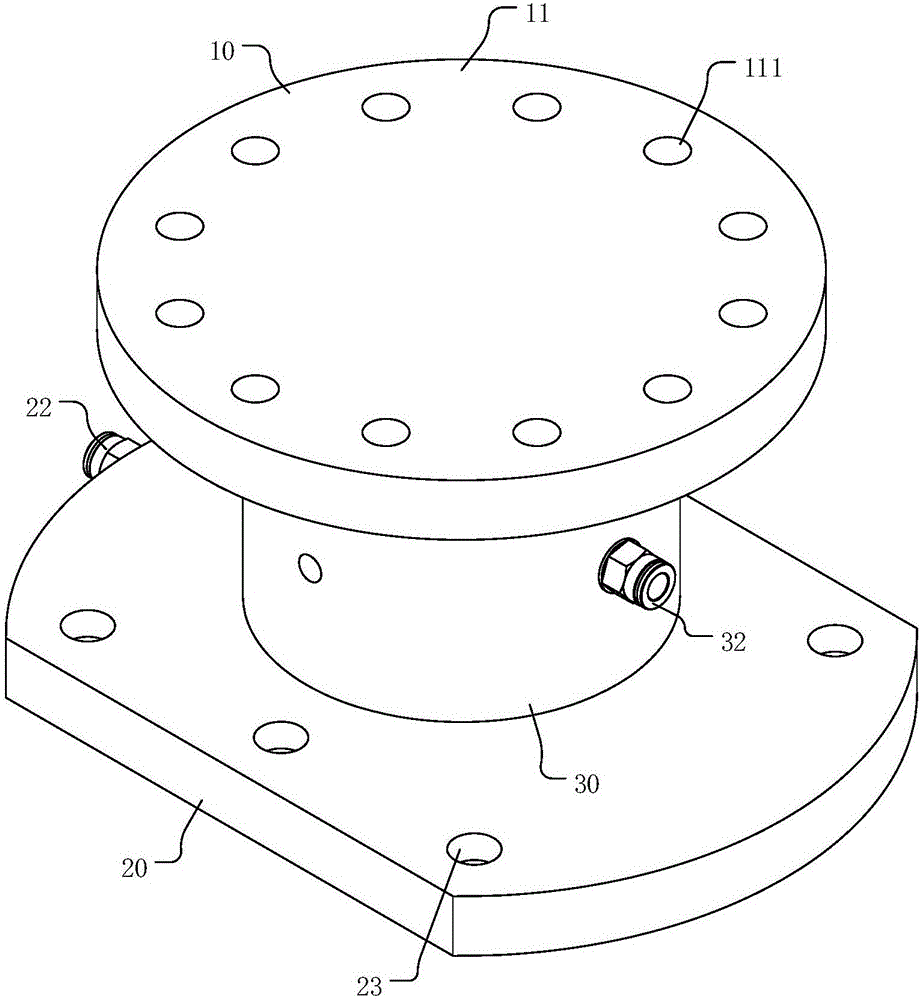
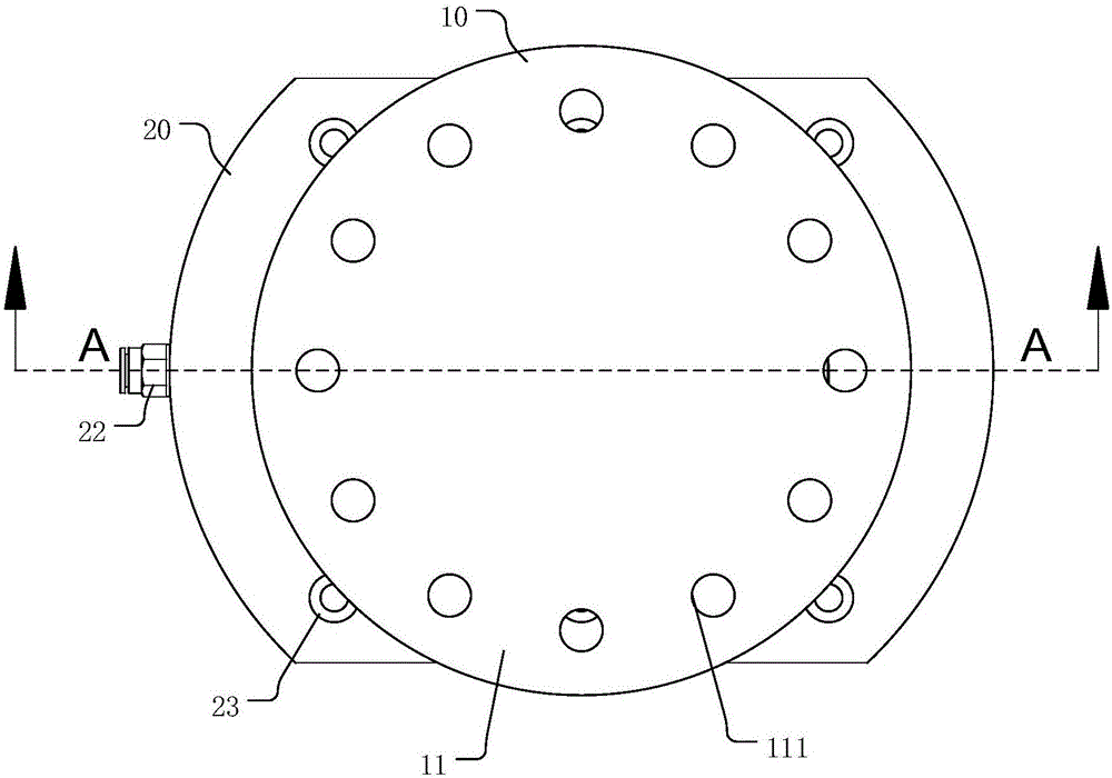
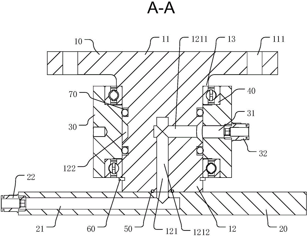
The invention discloses a pneumatic component installing structure, comprising a pneumatic component connecting structure and a gas supply connecting structure, wherein the gas supply connecting structure is internally provided with a first gas supply channel, and the pneumatic component connecting structure is internally provided with a second gas supply channel; the gas supply connecting structure can be rotated relatively to the pneumatic component connecting structure. The pneumatic component installing structure also comprises a connecting channel used for communicating the first gas supply channel with the second gas supply channel and extending in the direction of relative motion of the gas supply connecting structure to the pneumatic component installing structure. In the pneumatic component installing structure provided by the invention, the gas supply connecting structure able to move relatively to the pneumatic component installing structure is arranged to ensure that a gas supply pipeline is not driven to move in operation of the pneumatic component, so that smooth gas supply of the gas supply pipeline to the pneumatic component can be ensured, but also damage to the gas supply pipeline due to movement can be prevented.

Description

technical field [0001] The invention relates to the technical field of industrial processing automation, in particular to a pneumatic component installation structure. Background technique [0002] In recent years, with the introduction of "Made in China 2025", a whirlwind of intelligent manufacturing has been set off in various parts of China. The use of industrial robots is increasing, and the demand for industrial robot fixtures is also increasing, of which pneumatic fixtures account for a large Proportion. As we all know, the sixth axis of industrial robots can rotate at a large angle. The fixture installed on the sixth axis has an air supply pipe, and the large-angle rotation will cause knotting and winding, which will affect the normal air supply. Contents of the invention [0003] In view of this, the present invention provides a pneumatic component installation structure capable of avoiding knotting of the air supply pipeline. [0004] In the first aspect, a pneu...

Claims


Application Information

Patent Timeline
Patent Type & Authority Applications(China)
IPC IPC(8): B25J9/00F17D1/065
CPCF17D1/065B25J9/0009
Inventor 李亮汤琮然陶通涓钟泳李东阳陈雪峰余建辉唐严清何强锋
Owner ZHUHAI GREE INTELLIGENT EQUIP CO LTD
Why Eureka
Try Eureka