Making method of siphonic air incrementer

A booster and siphon type technology, which is applied in the field of preparation of siphon air booster, can solve the problems of high manufacturing cost, complicated preparation, and need for optimization, and achieves the reduction of preparation cost, simple preparation and simple overall structure Effect

Inactive Publication Date: 2017-01-11
许嘉乐
View PDF7 Cites 0 Cited by
  • Summary
  • Abstract
  • Description
  • Claims
  • Application Information

AI Technical Summary

Problems solved by technology

However, the applicant believes that, looking at the structure of the existing air extender, it is only a theoretical structure in physics. These structures can be prepared in theory, but once they are applied in industrial production, both It is necessary to consider the simplicity of preparation and the cost of preparation. For this reason, the principle structure given in physics is very complicated and troublesome to prepare, and the overall manufacturing cost is extremely high.
At the same time, the air extender structure proposed by the applicant in the above-mentioned patent application for insoles and soles also needs to be optimized.

Method used


Image

  • Making method of siphonic air incrementer
  • Making method of siphonic air incrementer
  • Making method of siphonic air incrementer

Examples


Embodiment Construction

[0034] The present invention will be further described below in conjunction with the accompanying drawings.

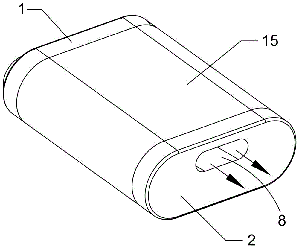
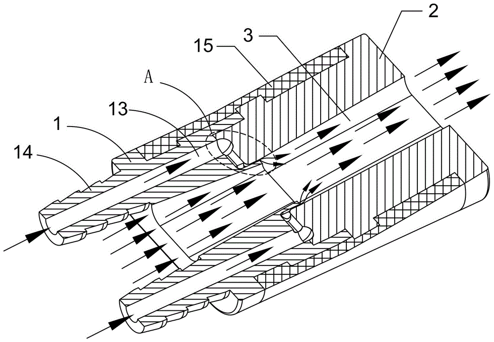
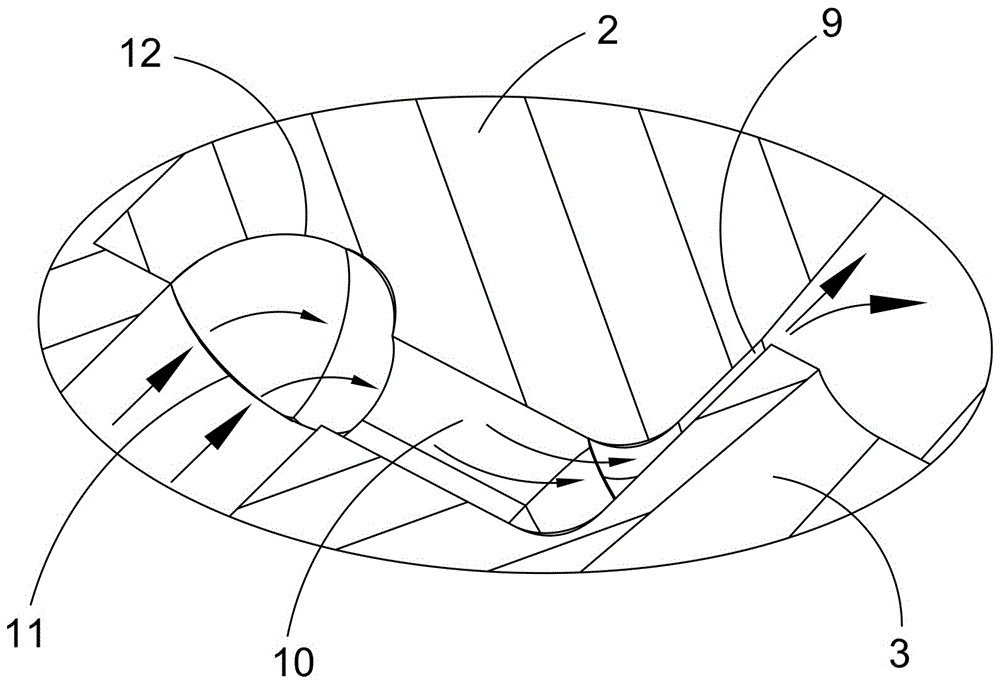
[0035] according to Figure 1 to Figure 6 As shown, the air extender of the present invention includes an intake pipe 1 and an exhaust pipe 2 of oblate structure, such as figure 1 As shown, the intake pipe 1 and the exhaust pipe 2 are preferably plastic or rubber injection-molded pipes, and they can also be metal molded parts or ceramic molded parts without considering factors such as cost and processing difficulty. The end of the air intake pipe 1 is connected to the front end of the exhaust pipe 2, and the air flow lumen 3 of the air intake pipe 1 and the exhaust pipe 2 are connected to form an air flow channel, such as figure 2shown. The end of the air intake pipe 1 is provided with a positioning cavity 4, and the positioning cavity 4 is provided with a protruding connecting air nozzle 5, and the air flow tube cavity 3 of the air intake pipe 1 extends from the ai...


PUM


Abstract

The invention discloses a siphonic air incrementer. The tail end of an air inlet pipe is connected with the front end of an air exhaust pipe, an airflow pipe cavity of the air inlet pipe and an airflow pipe cavity of the air exhaust pipe are connected to form an airflow channel, and the tail end of the air inlet pipe is provided with a positioning concave cavity which is internally provided with an outwards convex connection air tap; the front end of the air exhaust pipe is provided with a connection end socket which is installed in the mode of being matched with the inner wall face of the positioning concave cavity; an airflow pipe cavity of the connection end socket surrounds the periphery of the connection air tap, and an air excitation gap is reserved between the airflow pipe cavity of the connection end socket and the connection air tap; and the air inlet end of the air excitation gap receives an airflow output by an external compressed air source supply device, and the air outlet end of the air excitation gap is arranged to face the airflow direction of the airflow pipe cavity. Meanwhile, the invention discloses a making method of the air incrementer and a breathing air exchange shoe or pipeline air supply system with the air incrementer. The air incrementer and the making method thereof and the breathing air exchange shoe or pipeline air supply system with the air incrementer have the advantages that the structure is simple, the cost is low, and making is convenient and easy.

Description

[0001] This application is a divisional application of 2013101137878. The filing date of the original application: April 3, 2013. The name of the invention of the original application: an air extender and its preparation method and breathing ventilation with the air extender Shoe or ducted air supply system. technical field [0002] The present invention relates to the technical field of aerodynamic booster and its preparation and practical industrial application, in particular to an air booster and its preparation method and breathing ventilation shoes with the air booster or air ductwork. Background technique [0003] In aerodynamics, the invention and application of the air extender has provided a technological revolution for the development of various industries. Due to the application of the air extender, various industrial products have achieved a substantial leap in performance and quality . [0004] The inventor of the present invention has been engaged in the ...

Claims


Application Information

Patent Timeline
Patent Type & Authority Applications(China)
IPC IPC(8): F04F5/16A43B7/06F24F13/02
CPCA43B7/06F04F5/16F24F13/02
Inventor 许景贤
Owner 许嘉乐
Why Eureka
Try Eureka