Floating device of deep water unmanned submarine

A submersible and deep-water technology, which is applied to underwater ships, transportation and packaging, underwater operation equipment, etc., can solve problems such as inability to work, unopened floating bags, and increased volume of inflated gas to improve synchronization and uniformity , Avoid excessive local pressure and reduce the effect of inflation pressure

Inactive Publication Date: 2017-05-24
GENERAL ENG RES INST CHINA ACAD OF ENG PHYSICS
View PDF6 Cites 1 Cited by
  • Summary
  • Abstract
  • Description
  • Claims
  • Application Information

AI Technical Summary

Problems solved by technology

When the unmanned submersible is navigating in the deep water area (100m ~ 200m), the floating bag is restrained in the fairing of the submersible by folding, and the deep water pressure acts on the outer surface of the unmanned submersible. Entering between the fairing and the floating bag, the floating bag is in a strong folded state due to the action of water pressure. When the floating inflation mechanism quickly inflates the floating bag, the floating bag cannot be inflated synchronously due to the folding constraints, and the inflation speed is too high. Fast and the folded floating bag opens slowly under the limitation of water pressure, which may cause the local pressure near the inflation port of the floating bag to be too high and the floating bag has not yet opened; thus making the pressure near the inflation mouth exceed the pressure limit that the floating bag can withstand , leading to the rupture of the floating bag and the failure of inflation
[0003] At the same time, due to the high water pressure in the deep water area, the volume of the inflated gas that the flotation device of the unmanned submersible vehicle needs to carry increases relatively, so that the folding space of the floating bag is further compressed. zone inoperable state

Method used


Image

  • Floating device of deep water unmanned submarine
  • Floating device of deep water unmanned submarine
  • Floating device of deep water unmanned submarine

Examples


Embodiment Construction

[0018] The present invention will be further described below in conjunction with accompanying drawing:

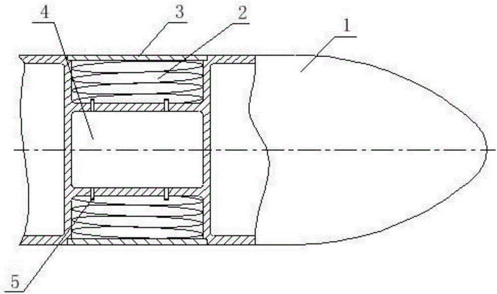
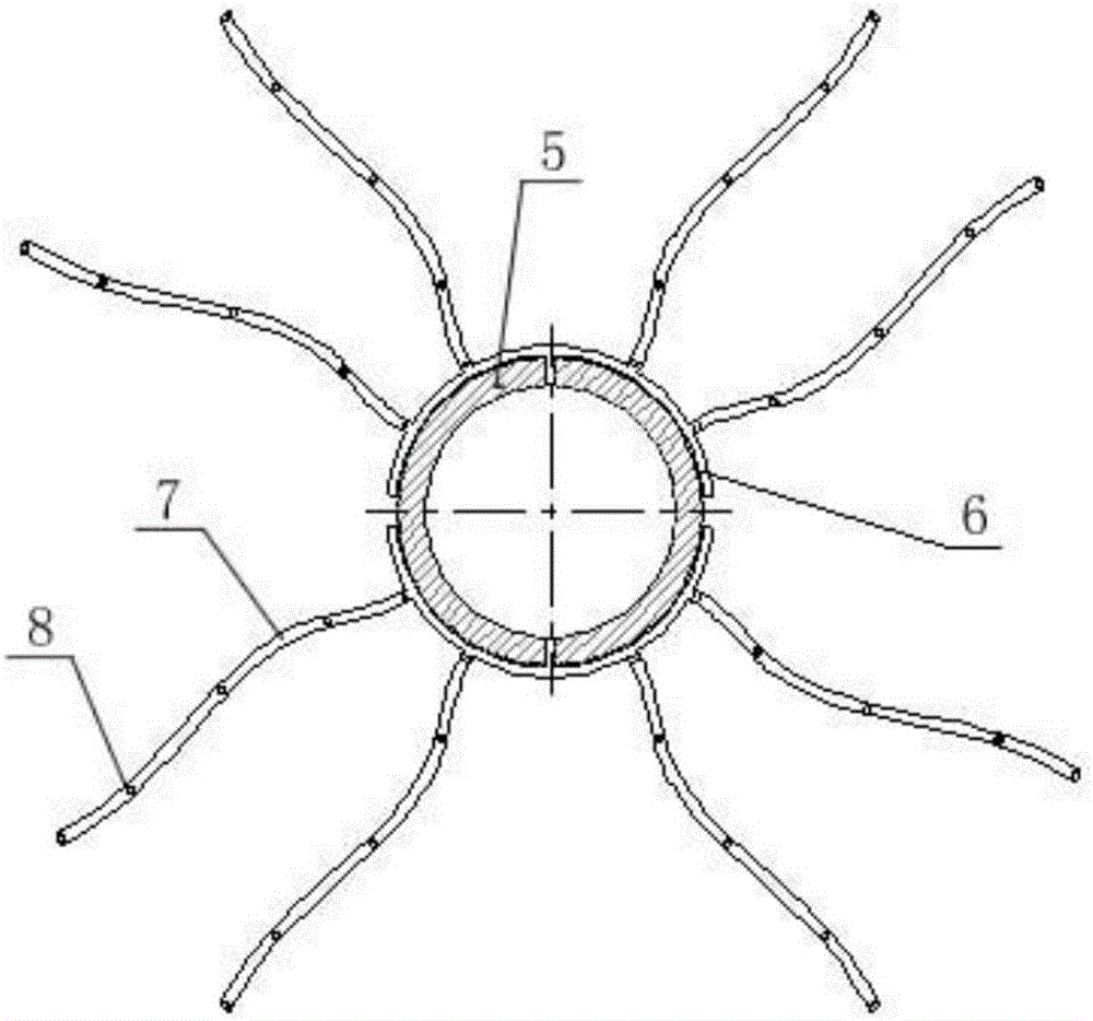
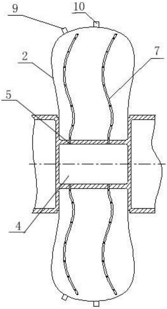
[0019] combine figure 1 , figure 2 and image 3 As shown, the present invention comprises a deep-water submersible 1, and the deep-water submersible 1 is provided with an inflatable chamber 4 for placing an air source, a fairing 3 and a floating bag 2 positioned in the fairing 3, and the floating bag 2 is provided with a safety valve 9, a differential The pressure valve 10 and the inflation nozzle 5 communicated with the interior of the inflation chamber 4, the inflation manifold 6 connected with the inflation nozzle 5 is arranged in the floating bag 2, and the inflation manifold 6 is connected with several flexible air guide tubes 7, and the upper edge of the flexible air guide tube 7 A number of exhaust holes 8 are arranged in sequence in the direction of the pipeline, and the inflatable nozzle 5, the inflatable manifold 6, the flexible air guide tube 7 and the floatin...


PUM


Abstract

The invention discloses a floating device of a deep water unmanned submarine. The floating device of the deep water unmanned submarine comprises a deep water submarine. The deep water submarine is provided with an inflatable chamber for holding a gas source, a fairing, and a floating bag positioned in the fairing. The floating bag is provided with a safety valve, a differential pressure valve, and an inflatable nozzle communicated to the interior of the inflatable chamber, the floating bag is internally provided with an inflatable manifold connected with the inflatable nozzle, the inflatable manifold is connected with a plurality of flexible air ducts, a plurality of exhaust vents are sequentially provided on the flexible air ducts along the pipeline, and the inflatable nozzle, the inflatable manifold, the flexible air ducts and the floating bag form a loop. According to the invention, the inflatable manifold is provided, so that gas becomes multi-point output from single-point input, the instantaneous inflation pressure around the inflatable nozzle is decreased, and the synchronization of inflation is improved; the flexible air ducts are additionally provided, so that gas flows to the folding end of the inside of the bag in the first time, the synchronization and uniformity of rapid inflation are improved, and the risk of bursting of the bag caused by too high local pressure due to uneven inflation is avoided.

Description

technical field [0001] The invention belongs to the field of marine technical equipment, and in particular relates to a floating device for a deep-water unmanned submersible. Background technique [0002] Deepwater unmanned submersibles need to be recovered at different depths, and the recovery method of floating bladder inflation is a commonly used recovery method. When the unmanned submersible is navigating in the deep water area (100m ~ 200m), the floating bag is restrained in the fairing of the submersible by folding, and the deep water pressure acts on the outer surface of the unmanned submersible. Entering between the fairing and the floating bag, the floating bag is in a strong folded state due to the action of water pressure. When the floating inflation mechanism quickly inflates the floating bag, the floating bag cannot be inflated synchronously due to the folding constraints, and the inflation speed is too high. Fast and the folded floating bag opens slowly under ...

Claims


Application Information

Patent Timeline
IPC IPC(8): B63G8/00B63G8/24
CPCB63G8/001B63G8/24B63G2008/002
Inventor 石运国姬永强甄文强杨奇袁鸣
Owner GENERAL ENG RES INST CHINA ACAD OF ENG PHYSICS
Why Eureka
Try Eureka