Deicing and lightning protection device for unmanned aerial vehicle

An unmanned aerial vehicle and lightning protection technology, which is applied in deicing devices, aircraft lighting protectors, aircraft electrostatic dischargers, etc., can solve the problems of poor conductivity of composite materials, smooth current discharge, damage to equipment, etc. Good effect, easy installation, weight reduction effect

Pending Publication Date: 2017-05-24
洛阳翰翔航空科技有限公司
View PDF2 Cites 6 Cited by
  • Summary
  • Abstract
  • Description
  • Claims
  • Application Information

AI Technical Summary

Problems solved by technology

In order to reduce the self-weight of the unmanned aerial vehicle and increase the endurance time in the design, the body of the unmanned aerial vehicle is made of a large number of composite materials, and the composite material has poor conductivity and cannot discharge the current smoothly like a metal skin. Therefore, when struck by lightning, Not only is it easy to damage the surface of the body, but also damage the equipment installed in the body
Under normal circumstances, the operation of unmanned aerial vehicles usually flies under good weather conditions, so deicing and lightning protection devices are not installed. With the expansion of the application field of unmanned aerial vehicles, especially the use of unmanned aerial vehicles for artificial rainfall operations Due to the particularity of the UAV, the UAV must fly through the clouds frequently in the cloud layer with conditioned rainfall, so the UAV is very easy to freeze, and the probability of being struck by lightning is also very high. Therefore, it is designed, developed and installed on the UAV. Protection against ice and lightning strikes is very necessary

Method used


Image

  • Deicing and lightning protection device for unmanned aerial vehicle
  • Deicing and lightning protection device for unmanned aerial vehicle
  • Deicing and lightning protection device for unmanned aerial vehicle

Examples


Embodiment Construction

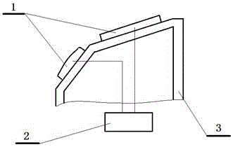
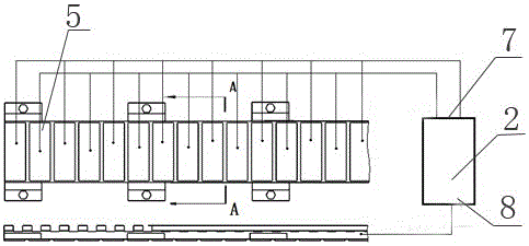
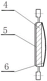
[0014] Provide the specific embodiment of the present invention below in conjunction with accompanying drawing as follows: figure 1 , figure 2 , image 3 As shown, a kind of deicing and anti-lightning device for unmanned aerial vehicle described in the present invention mainly consists of ultrasonic oscillator 1, ultrasonic controller 2, oscillator support 3, oscillating elastic body 4, piezoelectric ceramic sheet 5, elastic The film 6 is composed of; wherein: the ultrasonic oscillator 1 is installed on the oscillator bracket 3 in different combinations, and the oscillator bracket 3 is installed and fixed inside the wing of the aircraft (wings, flaps, tails, etc.); the ultrasonic controller 2 installed in the fuselage. Both ends of the ultrasonic controller 2 are provided with a controller AC voltage output terminal 7 and a controller common terminal 8 . Ultrasonic oscillator 1 is composed of oscillating elastic body 4, piezoelectric ceramic sheet 5, and elastic film 6; ul...


PUM


Abstract

The invention provides a deicing and lightning protection device for an unmanned aerial vehicle, which is suitable for flying safety devices for the unmanned aerial vehicles. According to the deicing and lightning protection device for the unmanned aerial vehicle, an ultrasonic controller (2) applies an alternating current voltage to a piezoelectric ceramic piece (5) through a lead; through inverse piezoelectric effects of the piezoelectric ceramic pieces (5), oscillation elastomers (4) generate standing wave or travelling wave oscillations; and the deformation applies an ultrasonic mechanical acting force to a freezing layer on the unmanned aerial vehicle so that the freezing layer is broken and falls off under an effect of wind power. The oscillation elastomers (4), which are connected section by section, are connected with pointed dischaging brushes (9); and a good conductive passage is provided to a lightning current so that great damage caused to the unmanned aerial vehicle can be avoided. The deicing and lightning protection device for the unmanned aerial vehicle has the advantages of good deicing effect, lightning protection, simple and compact structural design, light weight and so on and has no influence on the aerodynamic shape of the unmanned aerial vehicle.

Description

technical field [0001] The invention belongs to the technical field of unmanned aircraft flight safety, and mainly relates to an unmanned aircraft deicing and lightning protection device. Background technique [0002] Reports of aircraft (aircraft) being struck by lightning during flight are common. However, under normal circumstances, when a manned aircraft encounters lightning, the current can be discharged smoothly through the shielding of the electric skin on the aircraft, so as to avoid damage to the personnel and equipment in the aircraft, or the crash of the aircraft. But for the sake of aircraft safety, flights always try to avoid flying in the thunder cloud area. In addition, when the aircraft is flying in the clouds of supercooled water droplets, the outer surface of the aircraft is easy to freeze, especially the icing of the wings and tail will change the aerodynamic shape of the aircraft, affect the lift and control performance of the aircraft, and affect flight...

Claims


Application Information

Patent Timeline
Patent Type & Authority Applications(China)
IPC IPC(8): B64D15/16B64D45/02
CPCB64D15/16B64D45/02
Inventor 曹辉朱沛洪张奕龙杨成岳坤邹东孙希伟李丹红
Owner 洛阳翰翔航空科技有限公司
Why Eureka
Try Eureka