
Directional rotary plate feeding device

A technology of directional rotation and rotation of the main shaft, applied in packaging and other directions, can solve the problems of wasting time, lengthening the assembly line, and occupying a large area of ​​​​the whole machine.

Active Publication Date: 2019-05-24
ZHEJIANG HOPING MACHINERY
View PDF7 Cites 0 Cited by
  • Summary
  • Abstract
  • Description
  • Claims
  • Application Information

AI Technical Summary

Problems solved by technology

For example, the invention patent with the publication number CN 1422783A discloses a pneumatic stretching and swinging adsorption medicine plate conveying mechanism. The medicine plate conveying mechanism can move the medicine plate on the blister machine conveying line Adsorbed to the conveyor line of the cartoning machine, however, it is not difficult to see that the conveying mechanism of this pendulum structure can only be satisfied with one conveyor line of the cartoning machine. For a cartoning machine with more efficient conveyor lines, this This kind of plate feeding mechanism cannot realize the normal matching of the conveyor line of the blister machine and the cartoning machine; and after the swing type conveying method is transported once, it has to be turned back to pick up the next one, which wastes time and affects the plate feeding Efficiency; In addition, the drug plate conveying mechanism of this structure is only suitable for the layout where the conveying lines of the blister machine and the cartoning machine are parallel.

Method used


Image

  • Directional rotary plate feeding device
  • Directional rotary plate feeding device
  • Directional rotary plate feeding device

Examples


Embodiment Construction

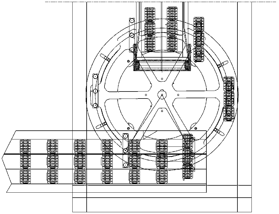
[0013] Such as image 3 As shown, the directional rotary plate feeding device acts as a mechanism between the conveyor belt of the blister machine and the conveyor belt of the cartoning machine, and plays the role of a manipulator, that is, the blister plate (also called a plate) on the conveyor belt of the blister machine The blister plates are transported to the conveyor belt of the cartoning machine, and the blister plates are packed by the cartoning machine.

[0014] From image 3 It can be seen that a conveyor belt of the blister machine has three assembly lines, indicating that the blister machine is 3 versions / cutting, and a conveyor belt of the cartoning machine has two assembly lines, and the two conveyor belts are perpendicular to each other. The conveying method of the directional rotary plate feeding device can send the three plates side by side on the three lines of the conveyor belt of the blister machine to one or more lines of the conveyor belt of the cartonin...


PUM


Abstract

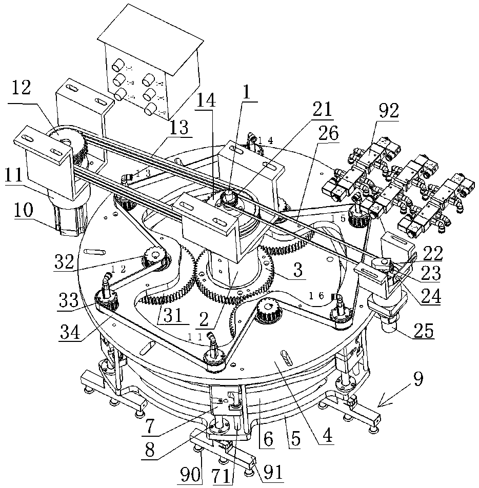
The invention relates to a directional rotating plate conveying device. The directional rotating plate conveying device comprises suction nozzle mechanisms and a revolution driving mechanism. Each suction nozzle mechanism comprises a suction nozzle base and suction nozzles, wherein the suction nozzles are arranged at the bottom of the suction nozzle base, and the suction nozzles are connected with an air source through an electromagnetic valve. The directional rotating plate conveying device is characterized in that the revolution driving mechanism is in transmission connection with a rotation main shaft, the rotation main shaft is rotationally arranged in a supporting base, and the supporting base is arranged on a rack; a lower rotary disc is arranged at the lower end of the rotation main shaft, an upper rotary disc is arranged above the lower rotary disc, and the upper rotary disc and the lower rotary disc are concentrically and fixedly connected; lifting mechanisms are arranged between the outer edge of the upper rotary disc and the outer edge of the lower rotary disc; and each lifting mechanism comprises a lifting sliding block and a lifting sliding rod, and the lifting sliding rods are arranged on the upper rotary disc and the lower rotary disc in a lifting manner. According to the directional rotating plate conveying device, revolution of the suction nozzles is driven through rotation of the upper rotary disc and the lower rotary disc, rotation of the lifting sliding rods is used for driving revolution of the suction nozzles to achieve self-orientation, accordingly, the suction nozzles rotate for feeding, and meanwhile the direction in the horizontal plane direction is kept unchangeable.

Description

technical field [0001] The present invention relates to a blister packaging machine, in particular to a directional rotary plate feeding device used on a blister packaging machine, of course, the directional rotary plate feeding device itself can also be used in the packaging field of other products. Background technique [0002] The blister packaging machine is generally composed of a blister machine and a cartoning machine. The blister machine completes the formation and packaging of the pharmaceutical blisters, and the cartoning machine completes the packaging of the pharmaceutical blisters. The conveyor belt of the traditional blister machine and the conveyor belt of the cartoning machine are generally set in parallel, and the drug plate is sucked and released from the conveyor belt of the blister machine to the conveyor belt of the cartoning machine through the drug plate conveying mechanism in the middle, so as to realize linkage. For example, the invention patent with...

Claims


Application Information

Patent Timeline
Patent Type & Authority Patents(China)
IPC IPC(8): B65B35/38B65B35/56
CPCB65B35/38B65B35/56
Inventor 杨益服李文磊
Owner ZHEJIANG HOPING MACHINERY
Learn More