Automatic feeding mechanism for machining

A technology of automatic feeding and machining, applied in conveyors, conveyor objects, transportation and packaging, etc., can solve problems such as inability to load pipe fittings, and achieve the effect of improving feeding efficiency

Active Publication Date: 2017-05-24
青岛张氏上佳科技有限公司
View PDF10 Cites 18 Cited by
  • Summary
  • Abstract
  • Description
  • Claims
  • Application Information

AI Technical Summary

Problems solved by technology

[0003] The purpose of the present invention is to solve the shortcomings in the prior art that the pipe

Method used


Image

  • Automatic feeding mechanism for machining
  • Automatic feeding mechanism for machining
  • Automatic feeding mechanism for machining

Examples


Embodiment Construction

[0015] The following will clearly and completely describe the technical solutions in the embodiments of the present invention with reference to the accompanying drawings in the embodiments of the present invention. Obviously, the described embodiments are only some, not all, embodiments of the present invention.

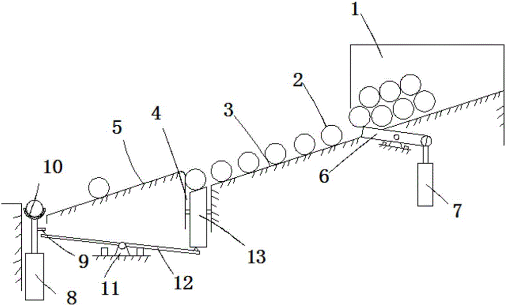
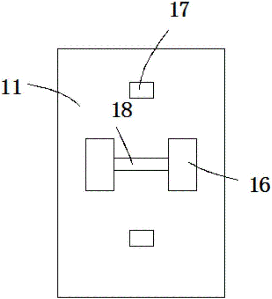
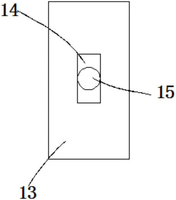
[0016] refer to Figure 1-3 , a machining automatic feeding mechanism, comprising a first slope 3 and a second slope 5, the first slope 3 and the second slope 5 are all inclined to the ground, and the upper end surface of the first slope 3 is equipped with a storage hopper 1, A pipe fitting 2 is placed in the storage hopper 1, a second cylinder 8 is provided on the side of the second slope 5 far away from the first slope 3, and a placement groove 10 for jacking up the pipe fitting 2 is installed on the output rod of the second cylinder 8, and the storage hopper The side wall of 1 is provided with a discharge hole, a slot 4 is reserved between the first slope 3 and th...


PUM


Abstract

The invention relates to the technical field of feeding mechanisms, in particular to an automatic feeding mechanism for machining. The automatic feeding mechanism for machining comprises a first inclined surface and a second inclined surface, wherein the first inclined surface and the second inclined surface are both inclined relative to the ground; a storage hopper is installed on the upper end surface of the first inclined surface; pipes are arranged in the storage hopper; a second air cylinder is arranged on the side, far away from the first inclined surface, of the second inclined surface; a holding trough used for jacking up the pipes is installed on an output rod of the second air cylinder; a discharging hole is formed in the side wall of the storage hopper; a clamping groove is reserved between the first inclined surface and the second inclined surface; a sliding block is arranged in the clamping groove; and the pipes penetrate out of the discharging hole, roll along the first inclined surface into an inner cavity of the clamping groove and are supported by the sliding block. The automatic feeding mechanism for machining can automatically stir, sequence and sequentially feed the pipes, effectively avoids the situation that the pipes are mutually blocked and can not be fed in order, has high feeding efficiency and is not prone to have faults.

Description

technical field [0001] The invention relates to the technical field of feeding mechanisms, in particular to an automatic feeding mechanism for machining. Background technique [0002] It is often necessary to use an automatic feeding mechanism in the machining process. The automatic feeding mechanism is usually a belt mechanism or a screw mechanism. Both the belt mechanism and the screw mechanism have the advantages of fast transportation and stable transportation when loading materials. During loading, the pipe fittings tend to be stacked or jammed on the loading platform so that the loading cannot be carried out in an orderly manner, which seriously affects the feeding efficiency. Contents of the invention [0003] The purpose of the present invention is to solve the disadvantage of the inability to orderly load pipe fittings in the prior art, and propose an automatic feeding mechanism for machining. [0004] In order to achieve the above object, the present invention a...

Claims


Application Information

Patent Timeline
IPC IPC(8): B65G47/14B65G47/82
CPCB65G47/1407B65G47/82B65G2201/0276
Inventor 吴涛陈晶晶王中华李丽丽秦华
Owner 青岛张氏上佳科技有限公司
Why Eureka
Try Eureka