
Solid-liquid separating system in sewage treatment

A technology for solid-liquid separation and sewage treatment, which is applied in the fields of water/sewage multi-stage treatment, flotation water/sewage treatment, water/sludge/sewage treatment, etc. It is easy to maintain and repair, improve the efficiency of sewage treatment, and achieve the effect of complete solid-liquid separation.

Active Publication Date: 2017-05-24
HUBEI JINHANJIANG REFINED COTTON
View PDF5 Cites 4 Cited by
  • Summary
  • Abstract
  • Description
  • Claims
  • Application Information

AI Technical Summary

Problems solved by technology

[0002] When treating the sewage produced by refined cotton production, it is necessary to use air flotation to separate the impurities in the sewage from the sewage. The sludge formed after the solid-liquid separation will naturally float to the water surface and be removed. After the sewage is discharged into the sedimentation tank Precipitation treatment, further solid-liquid separation and precipitation of fine impurities suspended in sewage, this method is one of the common methods of sewage treatment, but the current air flotation device and sedimentation device have the following shortcomings in the process of use, One is that the chemicals added during air flotation are not fully mixed with the sewage, and the solid-liquid separation is not thorough enough; the other is that when cleaning the floating dirt, the current scraping structure design is not reasonable enough, and the failure rate is high; It is more troublesome to remove the sludge after the sedimentation is completed. The water in the pool must be drained before removing the sludge, which not only affects the normal process of sewage treatment, but also requires a large workload for sludge removal, which cannot fully meet the needs of current sewage treatment.

Method used


Image

  • Solid-liquid separating system in sewage treatment
  • Solid-liquid separating system in sewage treatment

Examples


Embodiment Construction

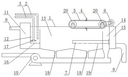
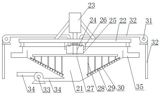
[0013] Depend on figure 1 and figure 2 As shown, the solid-liquid separation system in sewage treatment is composed of a solid-liquid separation floating device and a solid-liquid separation sinking device. Mud scraper 4, mud scraper conveyor chain 5, mud scraper drive motor 6, water delivery pipe 7, drain pipe 8, water inlet pipe 9 and sewage pump 10, the tank body 1 is separated from left to right by partitions There is a water inlet chamber 11, a mixing chamber 12, an air flotation chamber 13, a sewage discharge chamber 14 and a drainage chamber 15. The water inlet pipe 9 communicates with the water inlet chamber 11 of the pool body 1, and the water inlet chamber 11 and the mixing chamber 12 pass through The water hole 16 opened at the bottom of the partition is connected, and one end of the gas feeding pipe 2 and the drug feeding pipe 3 are respectively located at the bottom of the mixing chamber 12, so that the sewage gushing out from the bottom of the mixing chamber 12...


PUM


Abstract

The invention discloses a solid-liquid separating system in sewage treatment. A water inlet cavity, a mixing cavity, an air flotation cavity, a pollution discharge cavity and a water draining cavity are successively arranged in a pond through partitions respectively at intervals from left to right; a water inlet tube communicates with the water inlet cavity of the pond; the water inlet cavity communicates with the mixing cavity through a water hole formed in the bottom of the corresponding partition; one end of a gas feeding tube and one end of a chemical feeding tube are respectively positioned at the bottom of the mixing cavity; heights of the partitions on the left side and the right side of the air flotation cavity are lower than the height of an opening of the pond; a pollution discharge hole is formed in the bottom of the air flotation cavity; and a pollution discharge hole of the bottom of the pollution discharge cavity and a pollution discharge hole of the bottom of the air flotation cavity respectively communicate with a pollution discharge pump through pollution discharge tubes. The solid-liquid separating system in sewage treatment has the advantages that a chemical agent and sewage are mixed fully, solid-liquid separation is thorough, failure rate is reduced, the system is easy to maintain and repair, the sewage treatment effect is good, the treatment period is short, sludge can be discharged while precipitating, and the sewage treatment efficiency is improved effectively.

Description

technical field [0001] The invention relates to the technical field of sewage treatment devices, more specifically to the technical field of refined cotton sewage treatment devices. Background technique [0002] When treating the sewage produced by refined cotton production, it is necessary to use air flotation to separate the impurities in the sewage from the sewage. The sludge formed after the solid-liquid separation will naturally float to the water surface and be removed. After the sewage is discharged into the sedimentation tank Precipitation treatment, further solid-liquid separation and precipitation of fine impurities suspended in sewage, this method is one of the common methods of sewage treatment, but the current air flotation device and sedimentation device have the following shortcomings in the process of use, One is that the chemicals added during air flotation are not fully mixed with the sewage, and the solid-liquid separation is not thorough enough; the other...

Claims


Application Information

Patent Timeline
Patent Type & Authority Applications(China)
IPC IPC(8): C02F9/02
CPCC02F1/24C02F1/52
Inventor 周航旭周潞
Owner HUBEI JINHANJIANG REFINED COTTON
Learn More