Subsurface drainage ditch bottom hardening structure

A single and cover plate technology, applied in the field of hardened structure at the bottom of the drainage ditch, can solve the problems of difficult engineering, large engineering investment, easy accumulation of water at the bottom of the ditch, etc., and achieve the effect of reducing engineering investment, reducing engineering investment and shortening construction period.

Inactive Publication Date: 2017-05-24
李建新
View PDF0 Cites 4 Cited by
  • Summary
  • Abstract
  • Description
  • Claims
  • Application Information

AI Technical Summary

Problems solved by technology

[0003] Since the planned construction of the drainage ditch project has the lowest elevation in a watershed area, and the groundwater level is relatively high, it is extremely difficult to drain water and remove silt during construction. Due to serious water seepage at the bottom of the ditch, water is easy to accumulate at the bottom of the ditch. It is difficult to ensure the quality of concrete when pouring concrete, especially because of the high groundwater level. After removing the silt, the strength of the concrete cannot reach the designed technology after the mud formed by construction personnel and machinery working at the bottom of the ditch is mixed with the concrete. Requirements, ultimately leading to the failure of the renovation project to achieve the expected purpose, the shortened service life of the project after renovation, and large project investment

Method used


Image

  • Subsurface drainage ditch bottom hardening structure
  • Subsurface drainage ditch bottom hardening structure
  • Subsurface drainage ditch bottom hardening structure

Examples


Embodiment Construction

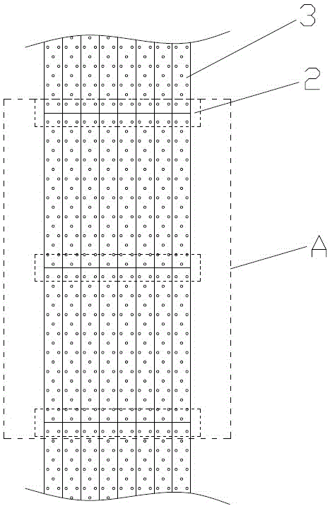
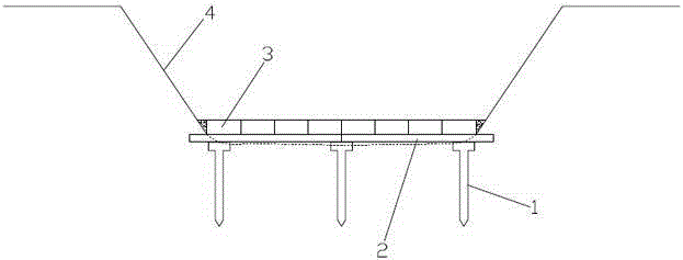
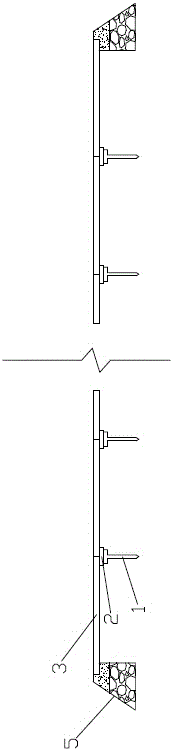
[0025] Such as Figure 1~4 As shown, a hardening structure at the bottom of the drainage ditch includes a bottom hardening device, which is arranged at the bottom of the drainage ditch, and the bottom hardening device includes a T-shaped pile 1, a beam 2, a cover plate 3, and a T-shaped pile 1 Set at the bottom of the drainage ditch, completely inserted into the ground, the top surfaces of multiple T-shaped piles 1 are on the same level, and beams 2 are arranged on multiple T-shaped piles 1, and multiple cover plates are arranged on the beams 2 3.

[0026] The cover plate 3 is a cover plate with through holes.

[0027] Cement mortar is poured in the gap between the cover plate 3 and the slope body 4 .

[0028] Both ends of the bottom hardening device are provided with thrust piers 5 to prevent longitudinal displacement.

[0029] The lower part of the thrust pier 5 is made of masonry rubble, and the upper part of the thrust pier 5 is made of cast-in-place concrete.

[0030]...


PUM


Abstract

The invention discloses a subsurface drainage ditch bottom hardening structure which comprises a bottom hardening device; the bottom hardening device is arranged at the bottom of a subsurface drainage ditch, and comprises a plurality of T-shaped piles, a cross beam and a plurality of cover plates; the T-shaped piles are arranged at the ditch bottom of the subsurface drainage ditch, and are completely inserted into the ground; the top surfaces of the T-shaped piles are located in the same horizontal plane; the cross beam is arranged on the T-shaped piles; and the cover plates are arranged on the cross beam. According to the subsurface drainage ditch bottom hardening structure, hardening is carried out through laying the cover plates with through holes on the bottom of the subsurface drainage ditch, and eutrophication of water in the subsurface drainage ditch can be avoided.

Description

technical field [0001] The invention relates to the technical field of construction, in particular to a hardened structure at the bottom of a stain discharge ditch. Background technique [0002] In the traditional drainage ditch improvement project, in order to effectively eradicate the growth of tall plants in the ditch and completely eliminate flood flow obstacles, during construction, the engineering measure for ditch bottom remediation is to backfill sand according to the vertical slope ratio after removing the silt in the ditch. Stone cushion, hardened cast-in-place concrete. [0003] Since the planned construction of the drainage ditch project has the lowest elevation in a watershed area, and the groundwater level is relatively high, it is extremely difficult to drain water and remove silt during construction. Due to serious water seepage at the bottom of the ditch, water is easy to accumulate at the bottom of the ditch. It is difficult to ensure the quality of concre...

Claims


Application Information

Patent Timeline
Patent Type & Authority Applications(China)
IPC IPC(8): E02B5/02E02B3/00
Inventor 李建新刘玲
Owner 李建新
Why Eureka
Try Eureka