Engine

An engine and pneumatic technology, applied in the direction of machines/engines, mechanical equipment, gas turbine devices, etc., can solve the problems of difficult to withstand high temperature, extremely high material requirements, affecting the thrust efficiency of aero-engines, and achieve a simple structure and high thrust efficiency. Effect

Inactive Publication Date: 2017-05-24
SHANGLING CO LTD
View PDF7 Cites 1 Cited by
  • Summary
  • Abstract
  • Description
  • Claims
  • Application Information

AI Technical Summary

Problems solved by technology

[0002] Traditional aero-engines have extremely high requirements on materials, and they are diffi

Method used


Image

  • Engine
  • Engine
  • Engine

Examples


Embodiment 1

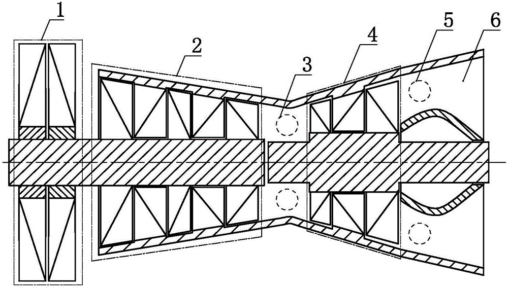
[0028] an engine such as figure 1 As shown, it includes a wind turbine 1, a compressor 2, a combustion chamber A 3, a turbine 4, a combustion chamber B 5 and a nozzle 6, the wind turbine 1 and the compressor 2 are set in transmission, and the The compressor 2 communicates with the turbine 4 via the combustion chamber A 3 , and the turbine 4 communicates with the nozzle 6 via the combustion chamber B 5 .

Embodiment 2

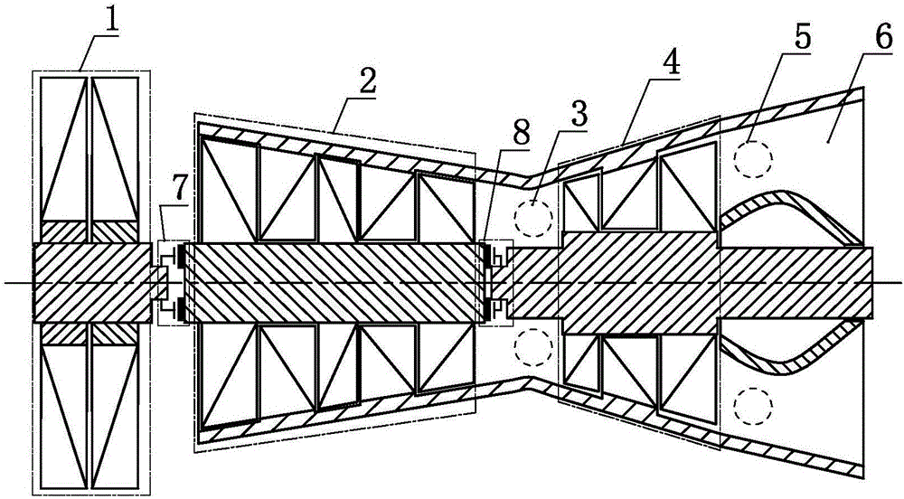
[0030] an engine such as figure 2 As shown, it includes wind turbine 1, compressor 2, combustion chamber A 3, turbine 4, combustion chamber B 5 and nozzle 6, and the compressor 2 is connected to the turbine 4 through the combustion chamber A 3 The turbine 4 communicates with the nozzle 6 through the combustion chamber B5, the wind turbine 1 is connected to the compressor 2 through the clutch A7, and the turbine 4 is connected through the clutch B 8 is set with the transmission of the compressor 2.

[0031] As a changeable embodiment, the present invention can also selectively select only the wind turbine 1 to be connected to the compressor 2 via the clutch A7, or only the turbine 4 to be connected to the compressor 2 via the clutch B8. The transmission setting of compressor 2 is described above.

Embodiment 3

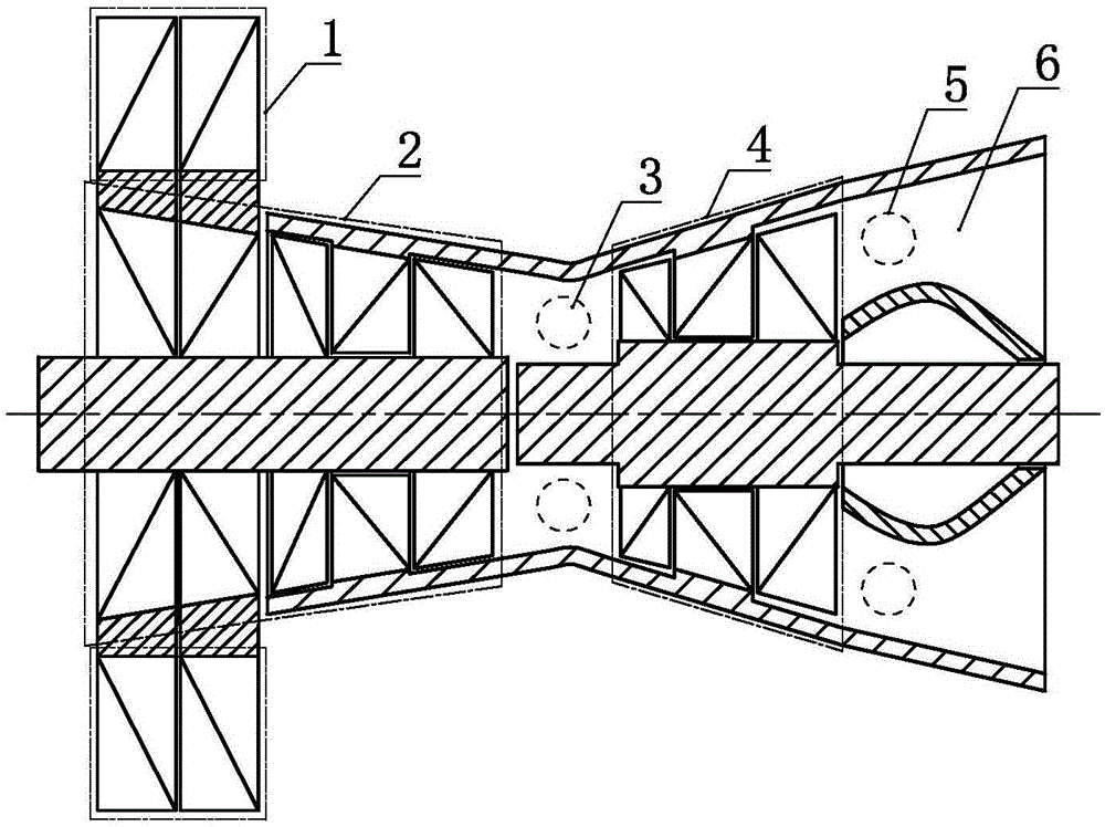
[0033] an engine such as image 3 As shown, it includes a wind turbine 1, a compressor 2, a combustion chamber A 3, a turbine 4, a combustion chamber B 5 and a nozzle 6, the wind turbine 1 and the compressor 2 are set in transmission, and the The compressor 2 communicates with the turbine 4 through the combustion chamber A 3, the turbine 4 communicates with the nozzle 6 through the combustion chamber B 5, the blade of the wind turbine 1 and the Part of the blades of the compressor 2 are radially co-bladed.

[0034] As a changeable implementation, Embodiment 3 of the present invention can further selectively select some or all of the blades of the compressor 2 that are radially co-bladed with the blades of the wind turbine 1 to communicate with the rest of the compressed air through the clutch A7. The blade transmission setting of the machine 2; and / or the transmission setting of the turbine 4 and the compressor 2 via the clutch B8.

[0035] As an alternative embodiment, in E...


PUM


Abstract

The invention discloses an engine. The engine comprises a pneumatic turbine, a gas compressor, a combustion chamber A, a turbine, a combustion chamber B and a spraying pipe; the pneumatic turbine and the gas compressor are arranged in a transmission manner; the gas compressor is communicated with the turbine by the combustion chamber A; and the turbine is communicated with the spraying pipe by the combustion chamber B. The engine has the advantages of simple structure and high thrust efficiency.

Description

technical field [0001] The invention relates to the field of thermal energy and power, especially to an engine. Background technique [0002] Traditional aero-engines have extremely high requirements on materials, and they are difficult to withstand high temperatures, which seriously affects the thrust efficiency of aero-engines. Therefore need to invent a kind of new engine. Contents of the invention [0003] In order to solve the above problems, the technical scheme proposed by the present invention is as follows: [0004] Scheme 1: An engine comprising a wind turbine, a compressor, a combustion chamber A, a turbine, a combustion chamber B and a nozzle, the wind turbine is set in transmission with the compressor, and the compressor is passed through the The combustion chamber A communicates with the turbine, and the turbine communicates with the nozzle through the combustion chamber B. [0005] Scheme 2: On the basis of scheme 1, the wind-driven turbine is further arr...

Claims


Application Information

Patent Timeline
IPC IPC(8): F02C3/00F02C3/04F02C3/14F02K3/00
CPCF02C3/00F02C3/04F02C3/14F02K3/00
Inventor 靳北彪
Owner SHANGLING CO LTD
Why Eureka
Try Eureka