Two-channel lateral rigidity semi-active hydropneumatic suspension

A technology of lateral stiffness and oil-pneumatic suspension, which is applied in the direction of suspension, elastic suspension, gas-hydraulic shock absorber, etc., and can solve problems such as limitations

Pending Publication Date: 2017-05-24
张宏如
View PDF9 Cites 7 Cited by
  • Summary
  • Abstract
  • Description
  • Claims
  • Application Information

AI Technical Summary

Problems solved by technology

However, it is limited to the suspension components, the working capacity, control capacity, system accuracy and cost composition of the electronic control system, and is greatly restricted in the application of large vehicles and popular products.

Method used


Image

  • Two-channel lateral rigidity semi-active hydropneumatic suspension
  • Two-channel lateral rigidity semi-active hydropneumatic suspension
  • Two-channel lateral rigidity semi-active hydropneumatic suspension

Examples


Embodiment Construction

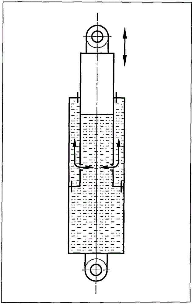
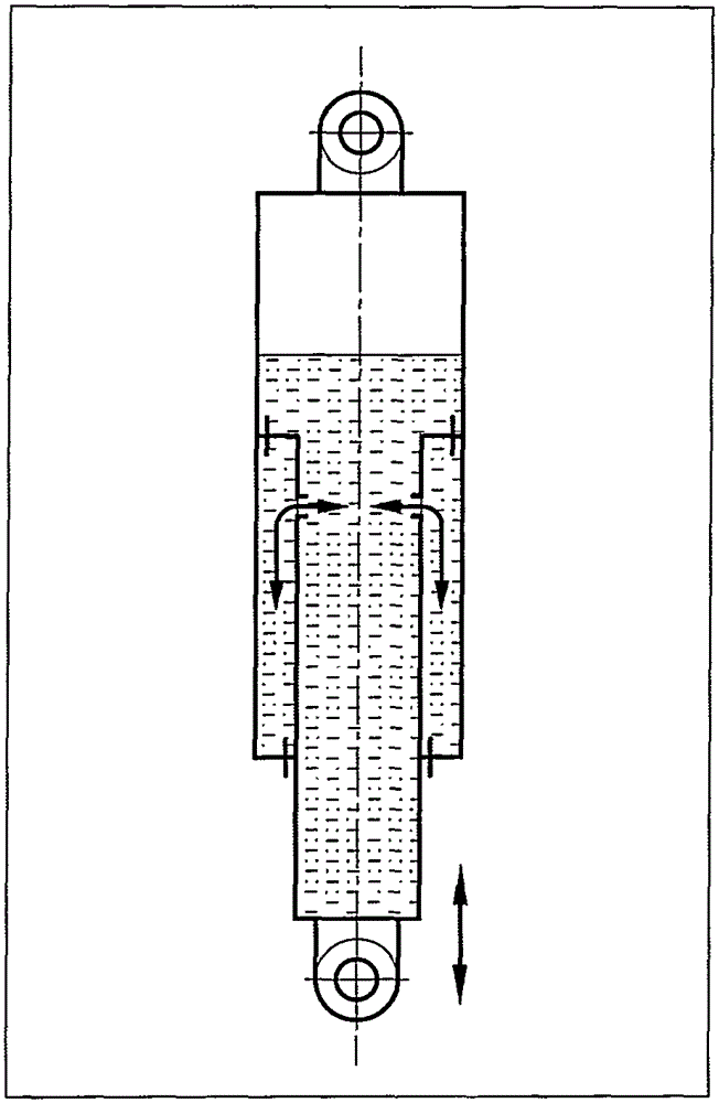
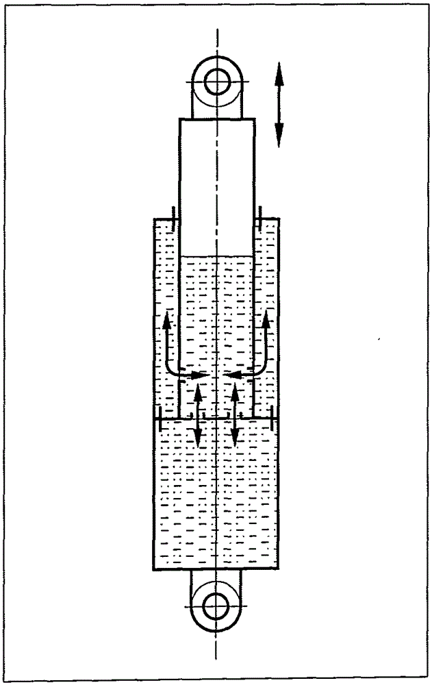
[0085] In this patent, the dual-channel lateral stiffness semi-active oil-pneumatic suspension adopts a left-right symmetrical layout structure, including a steering wheel 1, an angle synchronization control valve 2, a flow follower valve 3, a suspension cylinder 8, an accumulator 15, a control valve 16, and a control valve. Road 17, pipeline 18. The suspension cylinder 8 includes a piston rod 10 , a piston 11 , an internal control valve group 12 , a cylinder barrel 13 , and a sealing seat 14 . The cylinder 13 , the piston rod 10 and the piston 11 enclose the suspension cylinder inner cavity 20 (rodless cavity) inside the suspension cylinder 8 . Described cylinder barrel 13, seal seat ring 14 and piston rod 10, piston 11 are surrounded to form auxiliary oil chamber 21 (rod chamber) between the waist side wall of suspension cylinder 8. The auxiliary oil chamber 21 is filled with hydraulic oil and is completely isolated from the suspension cylinder inner chamber 20 . The suspe...


PUM


Abstract

The invention discloses a two-channel lateral rigidity semi-active hydropneumatic suspension adopting a bilateral symmetrical structure. The two-channel lateral rigidity semi-active hydropneumatic suspension comprises a steering wheel, an angle synchronous control valve, a flow follow-up valve, suspension cylinders, energy accumulators, control valves and pipelines. Each suspension cylinder comprises a piston rod, a piston, an inner control valve set, a cylinder barrel and a sealing socket ring. Each suspension cylinder internally comprises an auxiliary oil cavity and a suspension inner cavity which are completely isolated. Each suspension cylinder inner cavity comprises a cylinder barrel inner cavity and a piston rod inner cavity which communicate with each other through the corresponding inner control valve set in the middle so that a suspension cylinder inner cavity system can be formed. Each auxiliary oil cavity is externally connected with the corresponding control valve and the energy accumulator through the corresponding pipeline so that an external control loop can be formed. The angle synchronous control valve is connected with the control valves of the left external control loop and the right external control loop so that state control channs can be formed. The flow follow-up valve is connected with the cylinder barrel inner cavity of the left suspension cylinder inner cavity system and the cylinder barrel inner cavity of the right suspension cylinder inner cavity system so that pressure/flow follow-up channels can be formed. The two control channels are independent from each other, and the contained control loops/inner cavity systems contained are independent from each other. The angle synchronous control valve carries out synchronous control along with the steering wheel, and the flow follow-up valve carries out follow-up control along with the pressure of the left suspension cylinder inner cavity and the pressure of the right suspension cylinder inner cavity.

Description

technical field [0001] This patent relates to a vehicle active suspension structure, and specifically discloses a dual-channel lateral stiffness semi-active oil-air suspension. Background technique [0002] 1. Active and semi-active suspension [0003] Suspension is an important part of the vehicle chassis, located between the frame and the axle, undertakes the buffering and shock absorption function of the chassis to the ground, and has a significant impact on the ride comfort and handling stability of the vehicle. Suspension has several forms such as passive suspension, semi-active suspension, and active suspension, which reflect the degree of control over the chassis attitude, stiffness, damping and other mechanical properties as well as the vehicle's operating attitude. For ordinary vehicles, especially heavy-duty vehicles, the chassis usually adopts a passive suspension structure, the rigidity and damping structure are fixed, and the ride comfort and handling stability...

Claims


Application Information

Patent Timeline
Patent Type & Authority Applications(China)
IPC IPC(8): F16F9/06F16F9/512F16F9/58F16F9/34B60G17/048B60G17/056
Inventor 张宏如
Owner 张宏如
Why Eureka
Try Eureka