Multifunctional shock absorber with energy recovery function

An energy recovery and multi-functional technology, which is applied in the direction of controlling mechanical energy, magnetic circuit shape/style/structure, magnetic circuit rotating parts, etc., can solve the problem of damper vibration frequency detuning, lack of self-regulation ability, and environmental adaptation Poor ability and other problems, to achieve the effect of suppressing response, reducing weight, and obvious effect

Active Publication Date: 2021-12-10
SHANDONG UNIV
View PDF11 Cites 1 Cited by
  • Summary
  • Abstract
  • Description
  • Claims
  • Application Information

AI Technical Summary

Problems solved by technology

[0003] One of the current existing technologies is to consume the vibration energy of the building structure under the action of environmental excitation by installing dampers or vibration reduction devices on the building structure, but the current vibration control technology is mostly passive, such as the use of more TMD mass-tuned damper and TLD liquid-tuned damper, under the vibration of different intensities, will easily cause the vibration frequency of the damper to be out of tune with the vibration frequency of the main structure, so they have poor adaptability to the environment and do not have certain self-regulation capacity; and to achieve the ideal vibration reduction effect for structures with large dynamic response, a large space is required. In order to achieve the ideal vibration reduction effect, it is necessary to attach a large mass block to the top of the built building, thereby increasing the vertical load of the structure; In addition, high-rise buildings with large masses can have a whiplash effect under wind vibration or earthquake action

Method used


Image

  • Multifunctional shock absorber with energy recovery function
  • Multifunctional shock absorber with energy recovery function
  • Multifunctional shock absorber with energy recovery function

Examples


Embodiment Construction

[0033] It should be pointed out that the following detailed description is exemplary and intended to provide further explanation to the present application. Unless defined otherwise, all technical and scientific terms used herein have the same meaning as commonly understood by one of ordinary skill in the art to which this application belongs.

[0034] It should be noted that the terminology used here is only for describing specific implementations, and is not intended to limit the exemplary implementations according to the present application. As used herein, unless the context clearly dictates otherwise, the singular is intended to include the plural, and it should also be understood that when the terms "comprising" and / or "comprising" are used in this specification, they mean There are features, steps, operations, means, components and / or combinations thereof.

[0035] For the convenience of description, if the words "up", "down", "left" and "right" appear in the present i...


PUM


Abstract

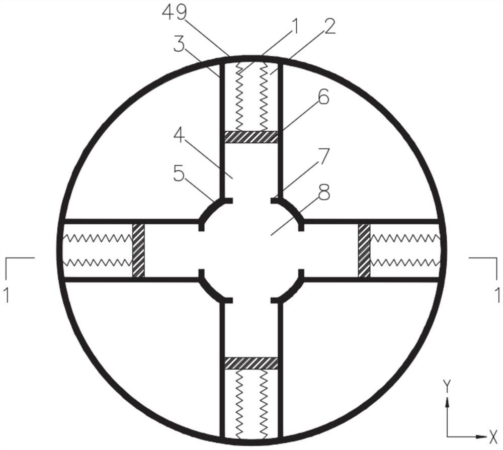
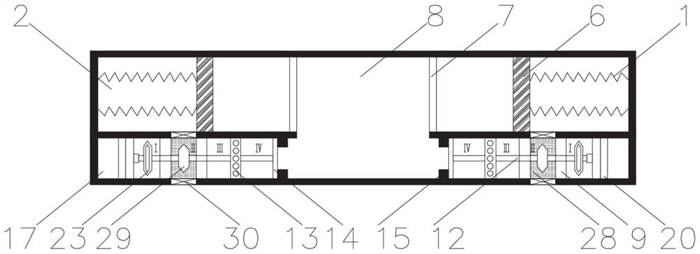
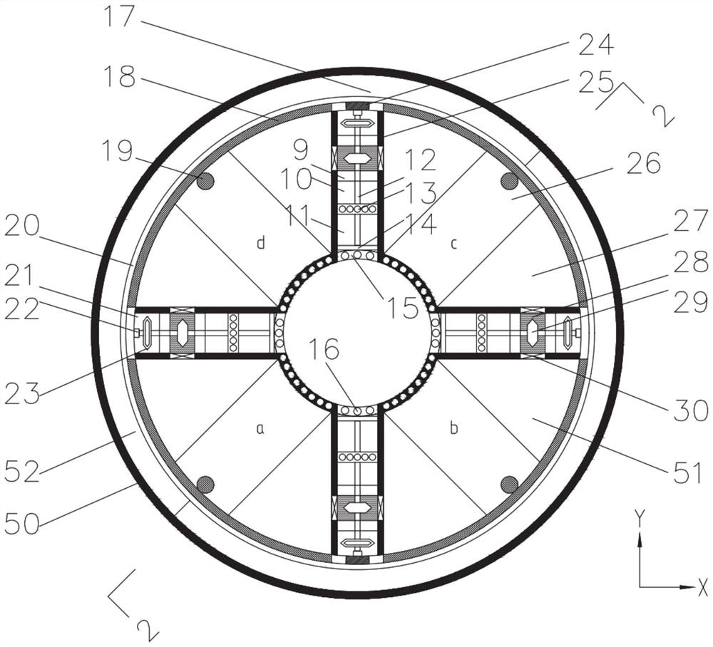
The invention discloses a multifunctional shock absorber with an energy recovery function. The multifunctional shock absorber comprises an upper barrel and a lower barrel, wherein the upper barrel is divided into a middle cavity and a functional cavity which communicate with each other, and the middle cavity is filled with air springs; a mass block piston is arranged in the functional cavity and is connected with the inner wall of the upper barrel through a spring; the lower barrel comprises an inner barrel and an outer barrel, and two permanent magnets are mounted on the inner side of the outer barrel; the inner barrel is divided into a middle cavity and functional cavities which communicate with each other, and the middle cavity is located in the center of the inner barrel and is filled with air springs; the functional cavities are located around the middle cavity; metal blades are arranged between every two adjacent functional cavities; each functional cavity is divided into four small cavities, an energy collecting device and a rotating wheel are arranged in each small cavity, each small cavity is filled with magnetorheological fluids, air springs and lead screw nut pairs, and screw rod pieces of the lead screw nut pairs penetrate through the four cavities and are connected with the two ends of the functional cavities; and the two middle cavities are connected through a bearing.

Description

technical field [0001] The invention relates to the field of vibration control of civil engineering, in particular to a multifunctional shock absorber with energy recovery, which is mainly used to reduce the vibration response of towering or long-span space structures under the action of environmental excitation. Background technique [0002] Due to the widespread use of lightweight and high-strength materials, new high-rise building structures usually have the characteristics of light weight, high strength, large aspect ratio, and low natural vibration frequency; therefore, these high-rise buildings are dynamic to the environment (such as wind, waves, Earthquakes, etc.) are becoming more and more sensitive. Under the excitation of monsoons and typhoons, the wind-induced vibration damage of high-rise buildings, the discomfort of residents in the buildings and the damage of living facilities are becoming more and more serious. It has become an urgent and important task for e...

Claims


Application Information

Patent Timeline
Patent Type & Authority Applications(China)
IPC IPC(8): E04B1/98E04H9/02H02K1/12H02K1/22H02K7/18
CPCE04B1/98E04H9/0215E04H9/023H02K1/12H02K1/22H02K7/1807
Inventor 刘玉萍马震刘俊才田利孟祥瑞罗贤超王晓阳杨萌
Owner SHANDONG UNIV
Why Eureka
Try Eureka