Automatic end cover locking mechanism for centrifugal mould

A locking mechanism and automatic technology, applied in the direction of coating, etc., can solve the problems of increased mold collection load, rear side panel extrusion recoil, mold material adhesion, etc., to improve the rotation dexterity and sealing degree, Improve the qualified quantity and project speed, and improve the effect of anti-interference

Inactive Publication Date: 2020-11-13
程金海
View PDF0 Cites 0 Cited by
  • Summary
  • Abstract
  • Description
  • Claims
  • Application Information

AI Technical Summary

Problems solved by technology

[0004] Aiming at the deficiencies in the prior art, the purpose of the present invention is to provide an automatic end cap locking mechanism for a centrifugal mold to solve the problem that the end cap lock sleeve of a centrifugal spinning die is usually operated with a cover type interspersed pin, and the side end of the pin When the hat frame is protected, it is easy to cause the rear side panel to be squeezed and recoiled to lift, thereby distorting the pin rod, resulting in a deviation in the fit of the secondary cover plate, and the mold processing operation with a gap will cause the molded material to stick to the side strip Excessive leftovers lead to a large amount of mold collection load in the later stage, and the flatness of the end face of the molding size is inclined, and the hinge force for the operation of tightening and inserting the end cover is insufficient, resulting in the continuous loss of the lock pin rod and causing fracture.

Method used


Image

  • Automatic end cover locking mechanism for centrifugal mould
  • Automatic end cover locking mechanism for centrifugal mould
  • Automatic end cover locking mechanism for centrifugal mould

Examples


Embodiment 1

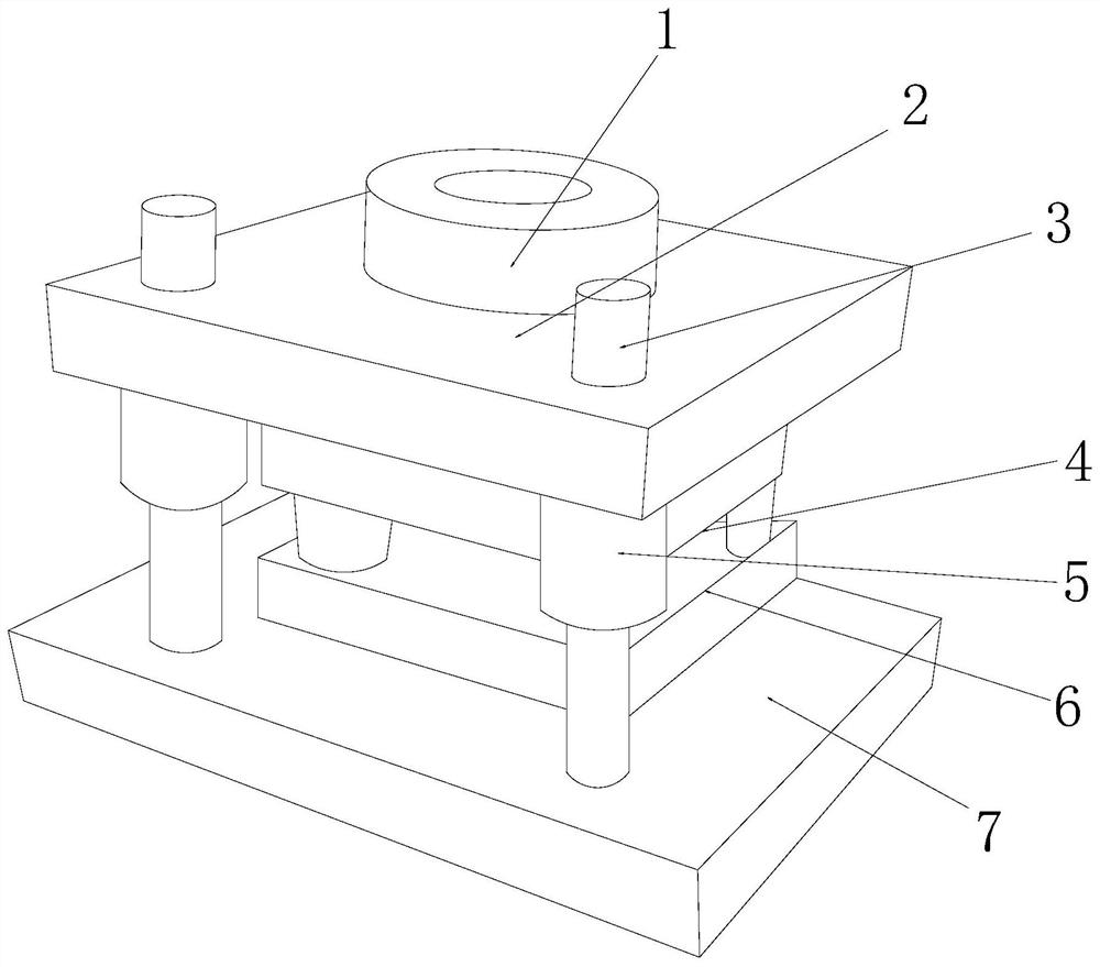
[0032] see Figure 1-Figure 6, the present invention provides a centrifugal mold automatic end cover locking mechanism, its structure includes: locking frame ring block 1, parting locking panel 2, pin rod 3, upper mold groove plate 4, beam sleeve 5, release The mold base 6, the liner plate 7, the parting locking panel 2 is mechanically connected with the mold locking frame ring block 1 and the axes are collinear, and the pin rods 3 are provided with two and respectively vertically penetrate the parting lock Tighten the left and right ends of the front side of the panel 2, the pin rod 3 and the beam sleeve 5 adopt an interference fit and the axes are collinear, and the upper mold groove plate 4 is mechanically connected with the demoulding base 6 and is parallel to each other, so The demoulding base 6 is close to the top surface of the liner plate 7 and is on the same level, and the upper mold groove plate 4 is close to the bottom surface of the parting locking panel 2 and is o...

Embodiment 2

[0039] see Figure 1-Figure 6 , the present invention provides a centrifugal mold automatic end cover locking mechanism, other aspects are the same as embodiment 1, the difference is:

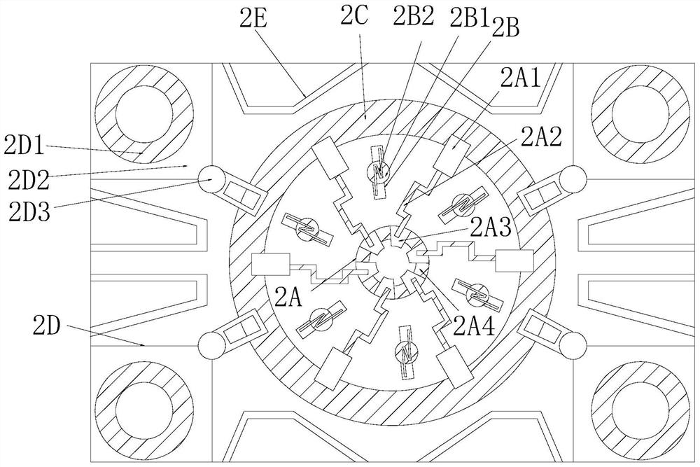
[0040] see figure 2 , the attached sheet buckle frame 2D is composed of a buckle block ring 2D1, a square plate 2D2, and a short buckle frame 2D3. The buckle block ring 2D1 is installed inside the square plate 2D2 and is in the same vertical position. On the straight side, the square plate 2D2 is buckled together with the buckle short frame 2D3, and the corners of the square plate 2D2 are cushioned by the buckle block ring 2D1 to form a clamping effect to ensure the protection of the pins. The completeness and fluency of interspersed.

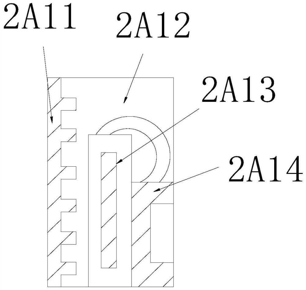
[0041] see Image 6 , the buckle block wheel ring 2D1 is composed of a seal ring 2D11, an elliptical pad gradient block 2D12, and a buckle column block 2D13. The gradient block 2D12 and the buckle column block 2D13 are installed inside the sealing ring 2D11...


PUM


Abstract

The invention discloses an automatic end cover locking mechanism for a centrifugal mould. The structure of the automatic end cover locking mechanism comprises a mould locking frame ring block, a parting locking panel, a column pin rod, an upper mould cavity plate, a beam sleeve, a mould releasing base and a lining plate. The mould locking frame ring block is matched with the parting locking panel;the mould locking frame ring block is inserted into a thick annular groove and a reinforcing rib panel is matched at a magnet propeller seat to form the overlying mobility of a magnet column block and a folding frame rib rod seat and the slot position locking operation of a bow-shaped propeller rod, so that a top cover of the mould forms a magnetic swirl lock effect, a rigid side is prevented from overlying column pins, and the interference rejection of the column pin rod is improved; a middle coverage locking effect is obtained at the axis end of a parting surface, the seam phenomenon of theparting surface in mould processing is improved, and the processing efficiency of seam tightening is improved; and moreover, the dressing link is saved through formed materials, the qualified quantity and engineering speed of assembly line batch processing are improved, and thus the swivel dexterity and sealed degree of the mould locking mechanism are improved.

Description

technical field [0001] The invention relates to an automatic end cover locking mechanism of a centrifugal mold, which belongs to the field of molds. Background technique [0002] The inner rotor of the centrifugal mold and the thimble of the cylinder have the effect of slow-release linkage and dislocation pressure, so that the upper and lower parting surfaces of the mold can be pressed with accurate mold precision, and then when the end cover of the later demoulding is lifted, the finished product of the small-pitch mold can be effectively released Surface layer, so as to facilitate the operation of mold taking and demoulding, and improve the ingenuity of mold processing. The shortcomings of the current technology that need to be optimized are: [0003] The end cover lock sleeve of the centrifugal spinning die is usually operated by covering and interspersing the pin, and when the side end cap frame of the pin is protected, it is easy to cause the rear side panel to be squee...

Claims


Application Information

Patent Timeline
Patent Type & Authority Applications(China)
IPC IPC(8): B29C41/38B29C33/20
CPCB29C33/20B29C41/38
Inventor 程金海
Owner 程金海
Why Eureka
Try Eureka