Pilot-operated blasting type pressure relief device

A pressure relief device and pilot-operated technology, which is applied in the direction of valve devices, functional valve types, safety valves, etc., can solve the problems of large deviation of opening pressure, inaccurate opening pressure, time-consuming, laborious and other problems, so as to avoid leakage problems and facilitate Observation, the effect of the overall compact structure

Inactive Publication Date: 2017-05-24
BEIJING AEROSPACE PETROCHEM TECH & EQUIP ENG CORP LTD
View PDF6 Cites 0 Cited by
  • Summary
  • Abstract
  • Description
  • Claims
  • Application Information

AI Technical Summary

Problems solved by technology

Conventional safety valves are not suitable for working conditions where the pressure is lower than 100 kPa. At low pressure, there are many problems such as inaccurate opening pressure, large excess pressure, and untimely response.
Although the bursting disc has good sealing performance and quick response, because of its direct contact with the medium, its discharge pressure is greatly affected by the corrosiveness and temperature of the medium, and when the pressure fluctuates or circulates, the stress of the bursting disc often reaches yield Above the limit, plastic deformation is easy to occur, which will lead to changes in its properties, premature blasting, and large deviations in opening pressure
[0004] In addition, once the conventional safety valve and bursting disc pressure relief device releases pressure, the production system must be shut down and disassembled for recalibration or replacement. Maintenance is time-consuming and laborious, which is not compatible with the current long-term operation and improvement of production efficiency. highly disproportionate demands

Method used


Image

  • Pilot-operated blasting type pressure relief device
  • Pilot-operated blasting type pressure relief device
  • Pilot-operated blasting type pressure relief device

Examples


Embodiment Construction

[0031] The present invention will be described in further detail below in conjunction with the accompanying drawings and specific embodiments.

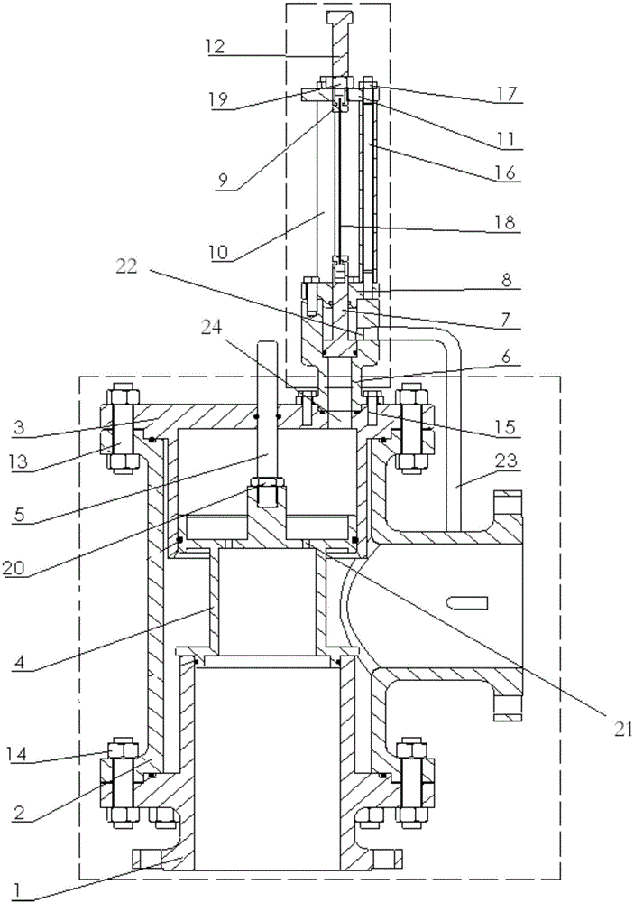
[0032] Such as figure 1 As shown, the pressure relief device is mainly composed of the main valve and the pilot valve. The main valve is composed of valve seat 1, valve disc 4, valve body 2, valve stem 5 and guide sleeve 3. Pilot valve is made up of pilot valve valve body 6, cover plate 8, pilot valve disc 7, depression bar 18, adjusting screw 12, sleeve 10, ferrule 9, pole 16, bracket cover 11.

[0033] The structure of the main valve is as follows: the lower end of the valve body 2 is fixedly installed on the flange of the valve seat 1, and is fixed by a stud 13 and a hex nut 14. A valve disc 4 is installed in the valve body 2, and the valve disc 4 is sealed and installed on the upper end of the valve seat 1. The upper end of the valve clack 4 is sealed and fixedly installed with the guide sleeve 3, and the upper end of the guide...


PUM


Abstract

The invention belongs to the overpressure protection technologies of pressure-bearing equipment and particularly discloses a pilot-operated blasting type pressure relief device which is composed of a pilot valve and a main valve. A piston type valve clack and a valve seat of the main valve serve as sealing pieces of the pressure relief device. When the valve clack is in close contact with the valve seat, sealing is achieved. When the valve clack is separated from the valve seat, pressure relief is achieved. A press rod is a critical component for controlling the device to be opened or closed and is installed outside a valve body of the pilot valve. One end of the press rod is connected with an adjusting screw on the pilot valve, and the other end of the press rod is connected with a valve clack of the pilot valve. The press rod is installed outside the valve body of the pilot valve as a load-bearing component and isolated from a medium, and influences of the temperature and corrosivity of the medium on the destabilizing pressure can be effectively avoided. The piston type valve clack and the valve seat form a sealing structure, the sealing effect is better, zero leakage can be achieved before opening, and the leakage problem happening when the pressure of a conventional safety valve approaches the opening pressure is solved.

Description

technical field [0001] The invention belongs to the overpressure protection technology of pressure-bearing equipment, and in particular relates to a pressure relief device. Background technique [0002] At present, pressure relief devices are widely used in various sectors of the national economy such as petroleum, chemical industry, power station, metallurgy, nuclear power, and national defense. With the improvement of production efficiency, relevant departments and enterprises have increasingly stringent requirements on environmental protection and safety. As an essential part of the emergency relief system, the performance and sealing requirements of the pressure relief device providing overpressure protection are also more stringent. [0003] Taking the ground flare system in the petrochemical industry as an example, the medium is usually flammable, explosive, poisonous and harmful chemical substances, and the operating pressure is relatively low, generally several thou...

Claims


Application Information

Patent Timeline
IPC IPC(8): F16K17/20F16K17/28
Inventor 郭善刚范军周浩岳大皓郭清云王德海刘屹
Owner BEIJING AEROSPACE PETROCHEM TECH & EQUIP ENG CORP LTD
Why Eureka
Try Eureka