

Air purifying unit
A technology of air purification and unit, which is applied in the direction of air conditioning system, mechanical equipment, air flow control components, etc., can solve the problems of insufficient buffer space, affecting the air intake efficiency, and affecting the air intake speed, etc., to achieve high primary filter efficiency and reduce The effect of using cost and convenient repeated use
- Summary
- Abstract
- Description
- Claims
- Application Information
AI Technical Summary
Problems solved by technology
Method used
Image

Examples
Embodiment 1
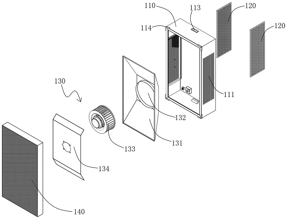
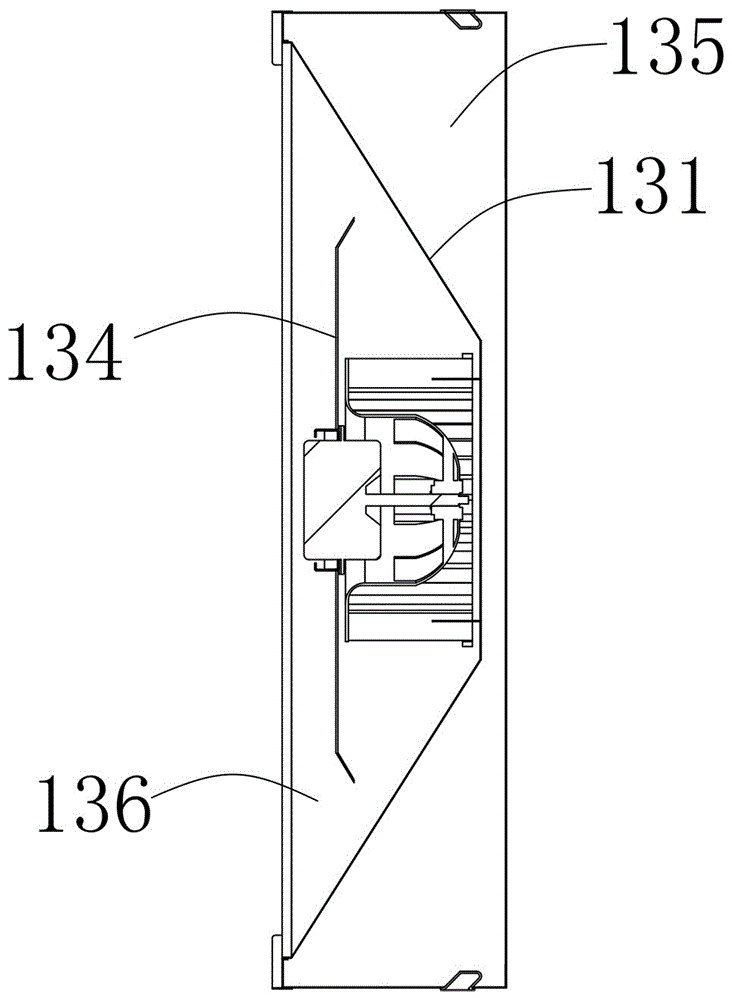
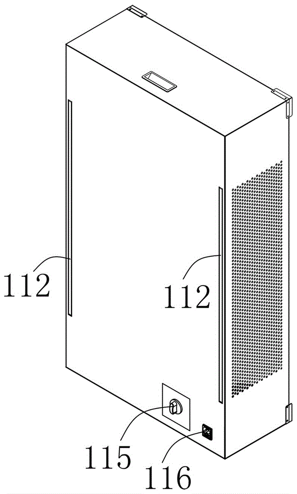
[0037] Such as Figure 1 to Figure 3 The shown air purification unit includes a housing 110, the two sides of the housing 110 are provided with air intake holes 111, the back of the housing 110 is respectively provided with filter slots 112 near the air intake holes 111, and the filter screen inserts The primary effect filter 120 is inserted in the groove 112, and the air filtered by the primary filter 120 is purified through the fan device 130 and the high efficiency filter 140 successively. A cavity 132 is arranged at the air inlet of the air partition 131, the fan 133 is installed in the cavity 132, and the fan bottom plate 134 is installed at the air outlet of the fan 133; the air passes through the effect of the fan 133, and the air partition 131 separates the housing 110 into The negative pressure chamber 135, the positive pressure chamber 136, and the fan bottom plate 134 guide the air in the positive pressure chamber 136 and promote the pressurization.
[0038] The ba...
Embodiment 2
[0043] Such as Figure 4 to Figure 6 As shown in the air purification unit, the air purification unit includes a housing 210, the two sides of the housing 210 are provided with air intake holes 211, the back of the housing 210 is respectively provided with filter slots 212 near the air intake holes 211, and the filter screen inserts The primary filter 220 is inserted into the groove 212, and is installed on the air outlet panel 260 at the air outlet of the casing 210. The air filtered by the primary filter 220 passes through the fan device 230, the activated carbon filter 240 and the high efficiency filter 250 successively. Purification, fan device 230 is made up of air partition 231, fan 233 and fan bottom plate 234, air partition 231 inlet is provided with a cavity 232, fan 233 is installed in cavity 232, fan bottom plate 234 is installed in fan 233 air outlet place; the air passes through the effect of the fan 233, the air partition 231 separates the housing 210 into a nega...
PUM
 Abstract
Description
Claims
Application Information