Quick dry system for tyre drier

A machine speed and tire technology, which is applied in the field of quick-drying system of tire dryer, can solve the problem of not being able to dry the glue, and achieve the effect of good air-drying effect and simple structure

Inactive Publication Date: 2017-05-24
卢文哲
0 Cites 1 Cited by

AI-Extracted Technical Summary

Problems solved by technology

The existing tires cannot be air-d...

Abstract

The invention discloses a quick dry system for a tyre drier. A rotating shaft is arranged in a mounting base at the front end and the rotating shaft extends into a mounting base at the back end, rollers are arranged on the rotating shaft, polish rods are arranged on the left and right sides of a retaining rod mounting base, a retaining rod is arranged on an inclined plate, a blowing pipe connecting box is arranged at the lower end of a piston rod, an air blower is arranged on the left side of the blowing pipe connecting box, a blowing pipe is arranged on the air blower, and the blowing pipe penetrates through the left side wall of the blowing pipe connecting box and extends to the lower side of the front end surface of the blowing pipe connecting box. According to the quick dry system for the tyre drier disclosed by the invention, the retaining rod is arranged to fix a tyre; and the position of the retaining rod on the inclined plate can be adjusted by rotating a handle, so that tyres in different dimensions are fixed; then the driving shaft is driven by a motor to rotate so as to drive the roller to rotate, and at the moment, the tyre between the two rollers also rotate, and the air blower is started to air-dry the glued tyre.

Application Domain

Drying gas arrangementsDrying machines with non-progressive movements +1

Technology Topic

EngineeringDrive shaft +3

Image

  • Quick dry system for tyre drier
  • Quick dry system for tyre drier
  • Quick dry system for tyre drier

Examples

  • Experimental program(1)

Example Embodiment

[0014] The technical solutions in the embodiments of the present invention will be clearly and completely described below in conjunction with the accompanying drawings in the embodiments of the present invention. Obviously, the described embodiments are only a part of the embodiments of the present invention, rather than all the embodiments. Based on the embodiments of the present invention, all other embodiments obtained by those of ordinary skill in the art without creative work shall fall within the protection scope of the present invention.
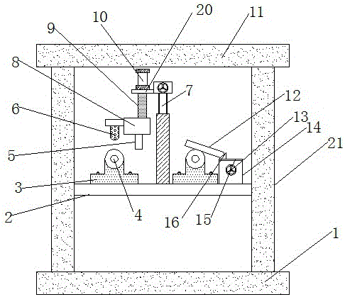
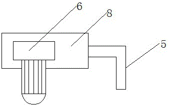
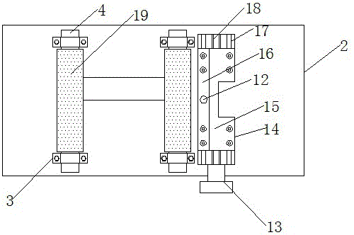
[0015] See Figure 1-3 , The present invention provides a technical solution: a quick-drying system for a tire dryer, comprising a support base 1, the upper and left sides of the support base 1 are provided with support columns 21, and the two support columns 21 are installed between The upper end of the supporting column 21 is provided with a supporting beam 11, the left and right ends of the mounting plate 2 are provided with mounting seats 3, the number of the mounting seats 3 is four, and the mounting seat 3 is provided in the front end The rotating shaft 4 extends into the mounting seat 3 at the rear end, the rotating shaft 4 is provided with a roller 19, and the right side of the mounting seat 3 is provided with a stop rod mounting seat 14 on the right side, and the stop rod is installed Polished rods 17 are provided on the left and right sides of the interior of the seat 14, and screw rods 18 are provided between the polished rods 17. The screw rod 18 is provided with a moving plate 15 threadedly connected to it, and an inclined plate is provided above the left end of the moving plate 15 16. The sloping plate 16 is provided with a stop rod 12, the front end of the stop rod mounting seat 14 is provided with a rotating handle 13, and the rotating handle 13 is connected to the front end of the screw 18, and the mounting seats 3 are arranged between the two ends. The lifting screw 7 is provided with a support platform 20 on the left side wall above the lifting screw 7, and a hydraulic cylinder device 10 is provided above the support platform 20, and a piston rod 9 is provided below the hydraulic cylinder device 10, and the piston rod 9 penetrates Supporting table 20, the lower end of the piston rod 9 is provided with an air supply pipe connecting box 8, the left side of the air supply pipe connecting box 8 is provided with a blower 6, the blower 6 is provided with an air supply pipe 5, the air supply The pipe 8 penetrates the left side wall of the air supply pipe connection box 8 and extends below the front end surface of the air supply pipe connection box 8. The mounting seat 3 is fixed on the mounting plate 2 by bolts, and the stop rod 12 is provided with rubber The left and right sides of the moving plate 15 penetrate the polished rod 17, and the tires to be air-dried are arranged between the rollers 19.
[0016] Working principle: First, place the rubber-sprayed tire between the two rollers 19, adjust the position of the stop lever 12 by rotating the handle 13, and fix the tire. At this moment, the blower 6 is started to dry the tire, and the piston rod 9 , The setting of the hydraulic cylinder device 10 and the lifting screw 7 can adjust the height of the air supply pipe 5 on the blower 6 to achieve different blowing effects.
[0017] Although the embodiments of the present invention have been shown and described, those of ordinary skill in the art can understand that various changes, modifications, and substitutions can be made to these embodiments without departing from the principle and spirit of the present invention. And variations, the scope of the present invention is defined by the appended claims and their equivalents.

PUM

no PUM

Description & Claims & Application Information

We can also present the details of the Description, Claims and Application information to help users get a comprehensive understanding of the technical details of the patent, such as background art, summary of invention, brief description of drawings, description of embodiments, and other original content. On the other hand, users can also determine the specific scope of protection of the technology through the list of claims; as well as understand the changes in the life cycle of the technology with the presentation of the patent timeline. Login to view more.

Similar technology patents

Body condition measuring device

InactiveUS20050234351A1simple structure
Owner:DENSO CORP

Magnetic cooling apparatus and control method thereof

ActiveUS20130180263A1simple structure
Owner:SAMSUNG ELECTRONICS CO LTD

Dual-Drivetrain of Power-Assist Vehicle

InactiveUS20100181130A1enhance uphill momentumsimple structure
Owner:CHOU WEN CHENG

Classification and recommendation of technical efficacy words

  • Simple structure
  • Good air drying effect

Sharing system for air-conditioning coat

InactiveCN107440179ASimple structureeasy to wear
Owner:QINGDAO HAIER AIR CONDITIONER GENERAL CORP LTD

Feeding device of sorter of batteries plate

InactiveCN101357717ASimple structurecooperate well
Owner:NANJING NORMAL UNIVERSITY

Emergency parachuting device and method for multiple-rotor unmanned aerial vehicle

InactiveCN103895870Aavoid aircraft crashSimple structure
Owner:SOUTH CHINA AGRI UNIV +1

Solar mixed flow air drying equipment

InactiveCN112414102AGood air drying effectprevent mildew
Owner:卢小良

Walnut airing machine for food processing

InactiveCN113606908AGood air drying effectgood effect
Owner:嘉兴希成杰科技有限公司
Why Eureka
Try Eureka