Fiber grating displacement meter in fiber grating series mode

A fiber grating string, fiber grating technology, which is applied in the direction of using optical devices, instruments, measuring devices, etc., can solve the problems that continuous measurement cannot be performed, only horizontal displacement can be measured, and only vertical displacement can be measured, and the preparation and maintenance can be achieved. Low cost, easy to operate, and good for production

Active Publication Date: 2017-05-24
QINGDAO TECHNOLOGICAL UNIVERSITY
View PDF5 Cites 7 Cited by
  • Summary
  • Abstract
  • Description
  • Claims
  • Application Information

AI Technical Summary

Problems solved by technology

At present, there are disclosed fiber grating displacement measurement devices, such as a large-range fiber grating displacement sensor with adjustable range and precision disclosed in Chinese patent 2016101592918, a fiber grating displacement sensor for measuring relative displacement disclosed in 2016202096060, and a fiber grating displacement sensor disclosed in 2016101658366 A fiber grating displacement sensor, etc., but these existing measuring devices or equipment cannot perform continuous measurement in bad weather, and the function of the displacement meter is too single, and can only measure horizontal displacement or only vertical displacement. Therefore, it is necessary to seek a A fiber grating displacement meter under the serial connection mode of the fiber grating adopts the method of connecting the displacement meter based on the spring and the equal-intensity beam in series, and the horizontal displacement of the point to be measured can also be measured while monitoring the horizontal displacement of the point. The vertical displacement, thus greatly saving the time and cost of engineering measurement

Method used


Image

  • Fiber grating displacement meter in fiber grating series mode
  • Fiber grating displacement meter in fiber grating series mode
  • Fiber grating displacement meter in fiber grating series mode

Examples


Embodiment 1

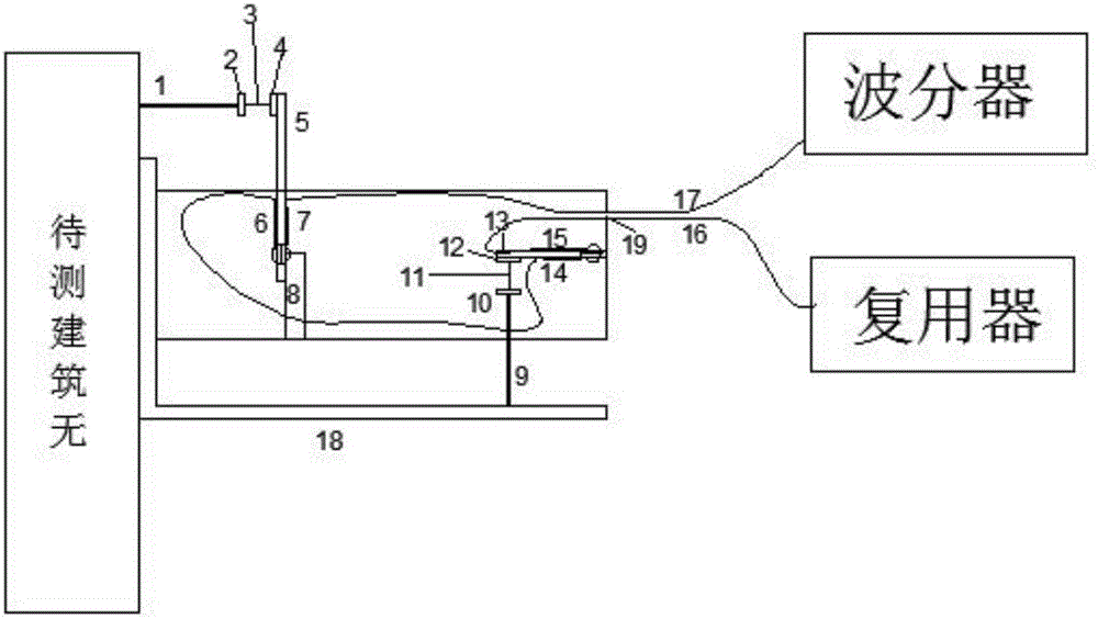
[0027] The main structure of this embodiment is the first probe rod 1, the first pad 2, the first spring 3, the second pad 4, the equal strength beam 5, the first fiber grating 6, the second fiber grating 7, and the third pad 8. The second probe rod 9, the fourth spacer 10, the second spring 11, the fifth spacer 12, the cantilever beam 13, the third fiber Bragg grating 14, the fourth fiber Bragg grating 15, the first pigtail 16, the second tail fiber 17, displacement meter fixing device 18 and housing opening 19; the first spacer 2 and the second spacer 4 are fixed on the displacement meter housing, and the two ends of the first spring 3 are fixedly installed with the first spacer 2 and the first spacer respectively. The second spacer 4, the first spring 3 is equipped with one end of the second spacer 4 and is fixed on the equal strength beam 5, and the other end is connected with the first probe rod 1, and the first probe rod 1 is connected with the building to be measured, T...


PUM


Abstract

The invention belongs to the technical field of construction engineering, and relates to a fiber grating displacement meter in a fiber grating series mode. A first cushion block and a second cushion block are respectively mounted at two ends of a first spring, one end of the first spring is fixed on an equal-strength beam, the other end of the first spring is connected with a first feeler lever, a first fiber grating and a second fiber grating are respectively stuck to the front and back of the equal-strength beam, and a third cushion block is fixedly mounted below the equal-strength beam; a third fiber grating and a fourth fiber grating are stuck to the front and back of a cantilever beam, a fifth cushion block and a fourth cushion block are mounted at the upper and lower ends of a second spring, one end of the second spring is fixed on the cantilever beam, the other end of the second spring is connected with a second feeler lever, and the second feeler lever is vertically mounted in the horizontal direction of a displacement meter fixing device. The fiber grating displacement meter is simple in structure, convenient to operate, scientific in principle and low in manufacturing and maintenance cost, and is suitable for simultaneously measuring horizontal displacement and vertical displacement of a point to be measured in various weathers.

Description

Technical field: [0001] The invention belongs to the technical field of construction engineering, and relates to an optical fiber grating displacement meter, in particular to an optical fiber grating displacement meter in a serial connection mode of optical fiber gratings. Background technique: [0002] In civil engineering, slope engineering and other fields, structural health monitoring is of great significance to the long-term operation of the project. At present, in the process of monitoring the displacement of building structures, in case of severe weather such as heavy rain and heavy snow, outdoor monitoring will not be carried out normally, and when severe weather occurs, it is also a critical period for data monitoring, and the lack of monitoring data will easily lead to damage to the building. A series of problems such as judging distortion of object displacement change; in addition, most of the measuring tools used in engineering are electronic sensors, such as the...

Claims


Application Information

Patent Timeline
Patent Type & Authority Applications(China)
IPC IPC(8): G01B11/02
CPCG01B11/02
Inventor 袁长丰王臣李聪明陈杨
Owner QINGDAO TECHNOLOGICAL UNIVERSITY
Why Eureka
Try Eureka