
Power grid maintenance monitoring method and system

A technology of power grid and power supply area, applied in the field of power grid maintenance monitoring method and system

Inactive Publication Date: 2017-05-24
JUANCHENG POWER SUPPLY CO STATE GRID SHANDONG ELECTRIC POWER CO
View PDF3 Cites 0 Cited by
  • Summary
  • Abstract
  • Description
  • Claims
  • Application Information

AI Technical Summary

Problems solved by technology

[0004] In view of this, the purpose of the present invention is to provide a grid maintenance monitoring method and system to solve the technical problem that the existing grid maintenance monitoring system is difficult to find the specific location of the fault in time

Method used


Image

  • Power grid maintenance monitoring method and system
  • Power grid maintenance monitoring method and system
  • Power grid maintenance monitoring method and system

Examples


Embodiment 1

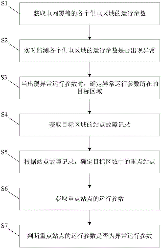
[0045] Such as figure 1 As shown, the embodiment of the present invention provides a grid maintenance monitoring method, including the following steps:

[0046] S1: Obtain the operating parameters of each power supply area covered by the grid.

[0047] Specifically, the operating parameters of each power supply area covered by the power grid can be obtained through the information network. Operating parameters may include current, voltage, phase angle, active power, reactive power, circuit temperature, etc. of each phase.

[0048] S2: Monitor in real time whether the operating parameters of each power supply area are abnormal.

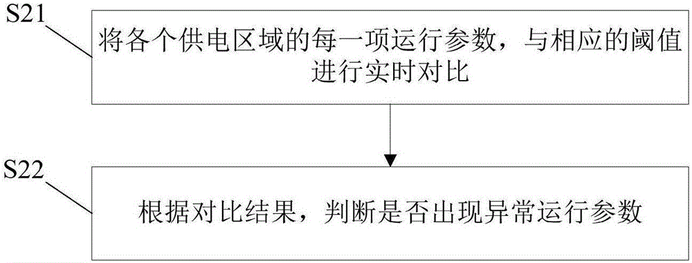
[0049] Such as figure 2 As shown, as a preferred solution, this step is specifically:

[0050] S21: Compare each operating parameter of each power supply area with the corresponding threshold in real time.

[0051] For each operating parameter, there is a corresponding threshold, which can be set according to the capacity and load of each area. ...

Embodiment 2

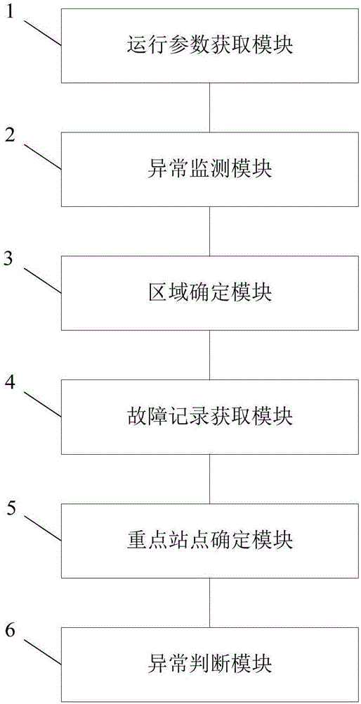
[0069] Such as image 3 As shown, the embodiment of the present invention provides a power grid maintenance and monitoring system, including an operation parameter acquisition module 1, an abnormality monitoring module 2, an area determination module 3, a fault record acquisition module 4, and a key station determination module 5.

[0070] The operating parameter acquisition module 1 is used to acquire the operating parameters of each power supply area covered by the power grid. The operating parameters of each power supply area covered by the grid can be obtained through the information network of the grid maintenance monitoring system. Operating parameters may include current, voltage, phase angle, active power, reactive power, circuit temperature, etc. of each phase.

[0071] The abnormality monitoring module 2 is used to monitor in real time whether the operating parameters of each power supply area are abnormal.

[0072] Such as Figure 4 As shown, as a preferred solut...


PUM


Abstract

The invention provides a power grid maintenance monitoring method and system, relates to the technical field of power grid maintenance and solves the technical problem that an existing power grid maintenance monitoring system has difficulty in finding specific fault sites in time. The power grid maintenance monitoring method comprises the steps of obtaining operation parameters of all power supply areas covered by a power grid; monitoring whether the operation parameters of all the power supply areas are abnormal in real time; determining a target area of the abnormal operation parameter when the abnormal operation parameter occurs; obtaining a site fault record of the target area; determining a key site of the target area according to the site fault record; obtaining an operation parameter of the key site.

Description

technical field [0001] The invention relates to the technical field of power grid maintenance, in particular to a method and system for power grid maintenance and monitoring. Background technique [0002] With the increasingly severe global energy problems, smart grid has become a hot research topic in various countries. The smart grid integrates modern advanced Internet of Things technology, network technology, sensor measurement technology, communication technology, computing technology, automation technology and intelligent control technology into the current physical grid to form a new smart grid. The smart grid establishes a panoramic perception network that completely covers power generation, transmission, transformation, distribution, consumption, and dispatching of the power system. [0003] The current power grid maintenance and monitoring system monitors the operation of the power grid by detecting various operating parameters during the operation of the power gri...

Claims


Application Information

Patent Timeline
Patent Type & Authority Applications(China)
IPC IPC(8): G01R31/08
CPCG01R31/086
Inventor 宁效鲁翟方杰张洪涛李胜森李巧雨南燕梅周天圣朱华军
Owner JUANCHENG POWER SUPPLY CO STATE GRID SHANDONG ELECTRIC POWER CO
Learn More