Inspection robot path planning method combining map grid with potential field method obstacle avoidance

An inspection robot and path planning technology, which is applied to instruments, two-dimensional position/channel control, vehicle position/route/height control, etc., can solve the problems of prolonged robot inspection time, low path planning efficiency, etc. The effect of completing efficiency, improving effectiveness, and short path distance

Active Publication Date: 2017-05-24
ELECTRIC POWER SCI RES INST OF GUIZHOU POWER GRID CO LTD +1
View PDF5 Cites 57 Cited by
  • Summary
  • Abstract
  • Description
  • Claims
  • Application Information

AI Technical Summary

Problems solved by technology

[0005] The technical problem to be solved by the present invention is to provide a path planning method for inspection robots that combines map grid and potential field method to avoid obstacles, so as to solve the problem that the path planning efficiency of robot inspection path planning in the prior art is not high, resulting in Technical issues such as extension of robot inspection time

Method used


Image

  • Inspection robot path planning method combining map grid with potential field method obstacle avoidance
  • Inspection robot path planning method combining map grid with potential field method obstacle avoidance
  • Inspection robot path planning method combining map grid with potential field method obstacle avoidance

Examples


Embodiment 1

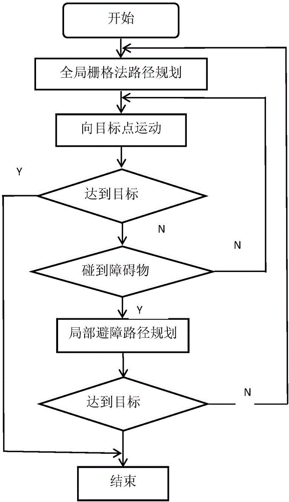
[0068] combine figure 1 , figure 1 It is an overall flowchart of the present invention. Firstly, the global path planning is carried out, and a global optimal path from the starting point to the target point is obtained by using the grid method; according to this optimal path, move to the target point, judge whether there is an obstacle, if not, continue to move to the target point, Otherwise, carry out local obstacle avoidance path planning; local obstacle avoidance path planning, use the artificial potential field method with variable parameters to plan obstacle avoidance path, judge whether to reach the target point, if not, continue to move towards the target point, otherwise end.

Embodiment 2

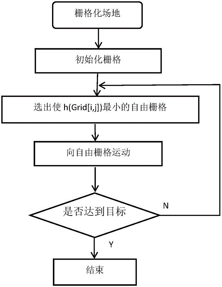
[0070] combine figure 2 , figure 2 It is a flow chart of the global path planning program of the present invention. First, grid the site, determine the target point, obstacle and the grid of the robot itself; initialize the grid, mark the grid with obstacles as 1, and mark the free grid as 0; search for the grid adjacent to the robot, and select From the free grid, define the evaluation function h(Grid[i,j]) to calculate the distance between the center point of this grid and the center point of the target grid: Grid[i,j] is the coordinates of the grid adjacent to the grid where the robot is located, and goal represents the grid coordinates of the target point; compare the h(Grid[i,j]) values ​​of each grid, and select h(Grid [i,j]) the smallest grid Grid[i,j] min , will Grid[i,j] min The grid is the grid where the robot will move to in the next step; judge whether the robot reaches the target point, if not, continue to search the adjacent grid of the robot, if it arrive...

Embodiment 3

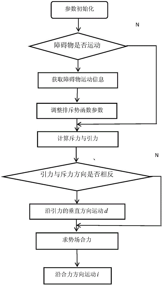
[0072] combine image 3 , image 3 It is a flow chart of the local obstacle avoidance path planning program of the present invention. First initialize the parameters of the potential field function, d1: the distance between the robot’s current position and the obstacle observed by the laser radar, k1: the repulsion weighting coefficient, temporarily set to 0.5, and adjust it according to the obstacle avoidance effect during the debugging process. d2: the distance between the position of the robot and the target point at this time, k2: the gravitational weighting coefficient, temporarily set to 0.5, and make specific adjustments according to the obstacle avoidance effect during the debugging process; then use the global laser radar sensor to judge the obstacles encountered Whether it is moving or not, then directly calculate the repulsive force and gravitational force according to the initialized parameters, otherwise, the motion vector of the obstacle and the position relativ...


PUM


Abstract

The invention discloses an inspection robot path planning method combining map grids with potential field method obstacle avoidance; the inspection robot path planning method comprises the following steps: 1, global grid method path planning: using the grid method to obtain the global optimal path from a start point to an object point; 2, moving to the object point: determining whether obstacles are encountered or not, moving to the object point is no obstacle is detected, planning a local obstacle avoidance path if an obstacle is detected until reaching the object point; 3, planning the local obstacle avoidance path, using the artificial potential field method with changeable parameters to carry out obstacle avoidance path planning, determining whether the object point is reached or not, returning to step 2 if not, and finishing the tour if the object point is reached. The inspection robot path planning method can solve the problems that the robot inspection path planning in the prior art is poor in efficiency, thus enlarging the robot inspection time.

Description

technical field [0001] The invention belongs to the technical field of obstacle avoidance path planning for inspection robots, and in particular relates to a path planning method for inspection robots combined with map grid and potential field method for obstacle avoidance. Background technique [0002] The inspection robot is a kind of mobile robot and is an important inspection equipment in the modern substation system. It is mainly used to replace humans to monitor various instruments and meters in the substation. The obstacle avoidance of inspection robot is a crucial part of robot path planning, and the different distribution of obstacles in the environment directly affects the planned path. The choice of obstacle avoidance algorithm is directly related to the effect of path planning. [0003] In practice, the robot's environment is neither completely known nor completely unknown in most cases, but partly known and partly unknown. In view of this situation, the existi...

Claims


Application Information

Patent Timeline
Patent Type & Authority Applications(China)
IPC IPC(8): G05D1/02
CPCG05D1/0214G05D1/0223G05D1/024G05D1/0257
Inventor 高吉普徐长宝罗显跃杨华龙征张历辛明勇王宇刘斌鲁彩江肖林林呈辉戴宇
Owner ELECTRIC POWER SCI RES INST OF GUIZHOU POWER GRID CO LTD
Why Eureka
Try Eureka