A Reference Synchronization Circuit for Resolver-to-Digital Conversion

A technology of reference synchronization and digital conversion, which is applied in the direction of angle demodulation through phase difference detection, etc., can solve problems such as the inability to quantify the actual compensation accuracy, poor practical operability, and phase-sensitive demodulation errors, so as to save the phase debugging link, Ease of application and improvement of angle detection accuracy

Active Publication Date: 2020-05-19
BEIJING MXTRONICS CORP +1
View PDF4 Cites 0 Cited by
  • Summary
  • Abstract
  • Description
  • Claims
  • Application Information

AI Technical Summary

Problems solved by technology

Based on this traditional tracking resolver-digital conversion method, there are hybrid integrated module products and analog (or digital) single-chip resolver-digital conversion circuit products. The phase-sensitive demodulation circuit references in these products are all resolver excitation inputs. Since the rotary is an electromechanical sensor, the internal sine and cosine coils are all inductive loads, which will cause the SIN and COS signals to lead in phase compared to the reference REF, resulting in an error in phase-sensitive demodulation. In high-precision angle measurement, this error has already It cannot be ignored that the traditional method is to correct the phase lag through an RC circuit before the SIN and COS signals are input into the single-chip circuit. Due to the matching accuracy of the resistance and capacitance values ​​and the temperature characteristics, this method is theoretically feasible, and the actual compensation accuracy cannot be quantified. Capacitor matching will introduce problems such as errors, poor temperature characteristics, and poor practical operability

Method used


Image

  • A Reference Synchronization Circuit for Resolver-to-Digital Conversion
  • A Reference Synchronization Circuit for Resolver-to-Digital Conversion
  • A Reference Synchronization Circuit for Resolver-to-Digital Conversion

Examples


Embodiment Construction

[0029] The present invention will be further introduced below with reference to the accompanying drawings.

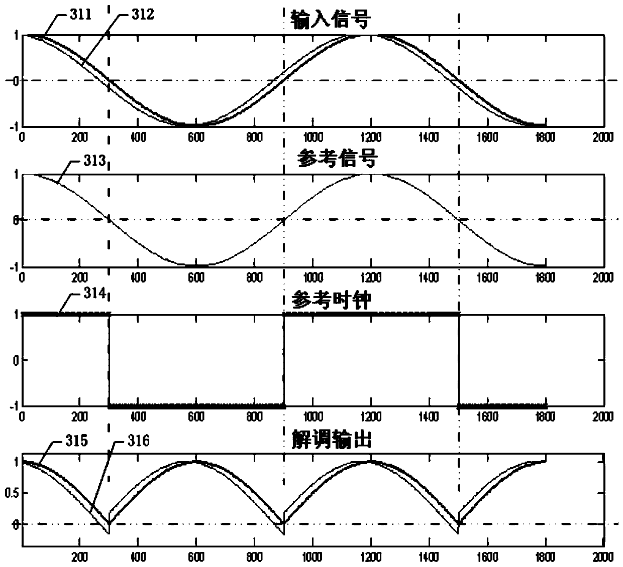
[0030] like image 3 As shown, the traditional phase-sensitive demodulation introduces demodulation error due to the reference phase error. The 312 signal is ahead of the 311 input signal, and the corresponding demodulated signals are 316 and 315 respectively. 315 is the real demodulated signal, and the 316 signal is obviously Distortion occurs and errors are introduced. A high-precision (eg, 16-bit resolution) resolver-to-digital conversion circuit must consider the demodulation error introduced by the phase of the reference signal, which can cause an angle conversion error of 1 to 10 LSBs.

[0031] Aiming at the existing high-precision resolver-to-digital conversion circuit phase-sensitive demodulation reference phase error and the introduction of demodulation errors, resulting in a decrease in angle detection accuracy, and the introduction of errors caused by extern...


PUM


Abstract

The invention discloses a reference synchronous circuit for resolver-to-digital conversion, which comprises a control transmission circuit, a multi-path selector and a comparator. The control transmission circuit receives a sine signal and a cosine signal which are generated by a resolver and three high bits of a resolver digital angle signal, and outputs two paths of signals A and B to the multi-path selector; the multi-path selector receives an externally input synchronization function enabling signal by a synchronization function enabling end, outputs resolver exciter reference signals REF_H and REF_L to the comparator when the synchronization function enabling signal is invalid, and outputs two paths of signals A and B to the comparator when the synchronization function enabling signal is valid; and the comparator compares sizes of two paths of input signals, and outputs a synchronous reference signal REF for providing a reference clock for a phase sensitive demodulation module so as to improve angle measurement accuracy of a resolver-to-digital conversion circuit.

Description

technical field [0001] The invention relates to a reference synchronous circuit for resolver-to-digital conversion. Background technique [0002] In the traditional tracking resolver-to-digital conversion, a phase-sensitive demodulation circuit is generally used to convert the AC angle error signal calculated by the shaft angle error into a DC error signal, and the DC error signal outputs a speed signal after an integral correction link to control the VCO output Pulse, the reversible counter counts the pulse, feeds back to the angle error calculation circuit and outputs the digitized angle. Based on this traditional tracking resolver-to-digital conversion method, there are hybrid integrated module products and analog (or digital) single-chip resolver-to-digital conversion circuit products. The phase-sensitive demodulation circuit references in these products are all resolver excitation inputs. Because the rotary is an electromechanical sensor, the internal sine and cosine c...

Claims


Application Information

Patent Timeline
Patent Type & Authority Patents(China)
IPC IPC(8): H03D3/18
CPCH03D3/18
Inventor 叶泽刚张奇荣朱红王浩
Owner BEIJING MXTRONICS CORP
Why Eureka
Try Eureka