A system and method for condensing and thermally rectifying gaseous fractions at the top of the tower

An overhead gas and fraction technology, which is applied in the field of rectification and energy saving, can solve the problems of safety, large energy consumption, large consumption, etc., and achieves the effect of wide usability and energy reduction.

Active Publication Date: 2019-10-25
河北美邦工程科技股份有限公司
View PDF11 Cites 0 Cited by
  • Summary
  • Abstract
  • Description
  • Claims
  • Application Information

AI Technical Summary

Problems solved by technology

[0002] Due to its excellent separation ability, rectification operation is widely used in various fields of life and production. It is an important unit operation in the separation process. However, the rectification process consumes a lot of energy, and the energy utilization rate is not high. According to statistics, traditional The total energy consumed by the rectification operation accounts for about half of the total energy consumption of industrial production, which is a key step that restricts the entire production process; for example, although the production process of propylene oxide technology by HPPO method is simple, the product yield is high, and it is in line with green Clean production requirements, but the production process needs to use a large amount of methanol as a solvent. After the product is separated, the methanol solvent must be rectified. However, in the operation of a conventional rectification system, the cooling condenser at the top of the tower generally uses cooling water to separate the gas phase at the top of the tower. The distillate is cooled and condensed, and part of the condensate is returned to the first tray at the top of the tower; the bottom reboiler generally uses external steam to heat and evaporate part of the liquid fraction at the bottom of the tower and then returns to the first tray at the bottom of the tower On the one hand, to maintain the rectification operation, on the one hand, the cooling condenser at the top of the tower needs to consume a large amount of cooling water; Improving the energy utilization rate in the rectification process, thereby reducing the energy consumed in the entire rectification process, has become the research focus of many scholars.
Chinese patent CN205287681U discloses a rectification energy-saving device for producing MBET. This device realizes accurate measurement of the temperature inside the tower by designing the heater and condenser of the rectification tower. Under the condition of ensuring the purity of the product, Reduce the temperature in the tower as much as possible to achieve the purpose of energy saving, but this method does not effectively use the heat from the top and bottom products of the rectification tower, and the energy saving effect is not very significant
Chinese patent CN204815741U discloses a rectification energy-saving device. This device extracts part of the material produced in the tower reactor, and the other part is turned into steam through throttling and expansion, and exchanges heat with the tower reactor feed liquid, and then enters the rectification tower through compression. , as reflux, the device effectively utilizes the energy generated by the tower kettle, which reduces the energy consumption of the rectification process to a certain extent, but does not make reasonable use of the large amount of latent heat at the top of the tower, and there is still a long way to go before the real energy saving and consumption reduction big gap
Chinese patent CN205549650U discloses a heat pump rectification system. The system is aimed at the ethanol rectification system. The ethanol vapor obtained at the top of the tower is compressed and heated, and then reused as a heat source for the reboiler. Although this system effectively utilizes the The heat brought out by the top stream, but the ethanol vapor is not suitable for direct compression, and there are safety hazards in the operation process, which limits the application field of the system to a certain extent

Method used


Image

  • A system and method for condensing and thermally rectifying gaseous fractions at the top of the tower
  • A system and method for condensing and thermally rectifying gaseous fractions at the top of the tower

Examples


Embodiment 1

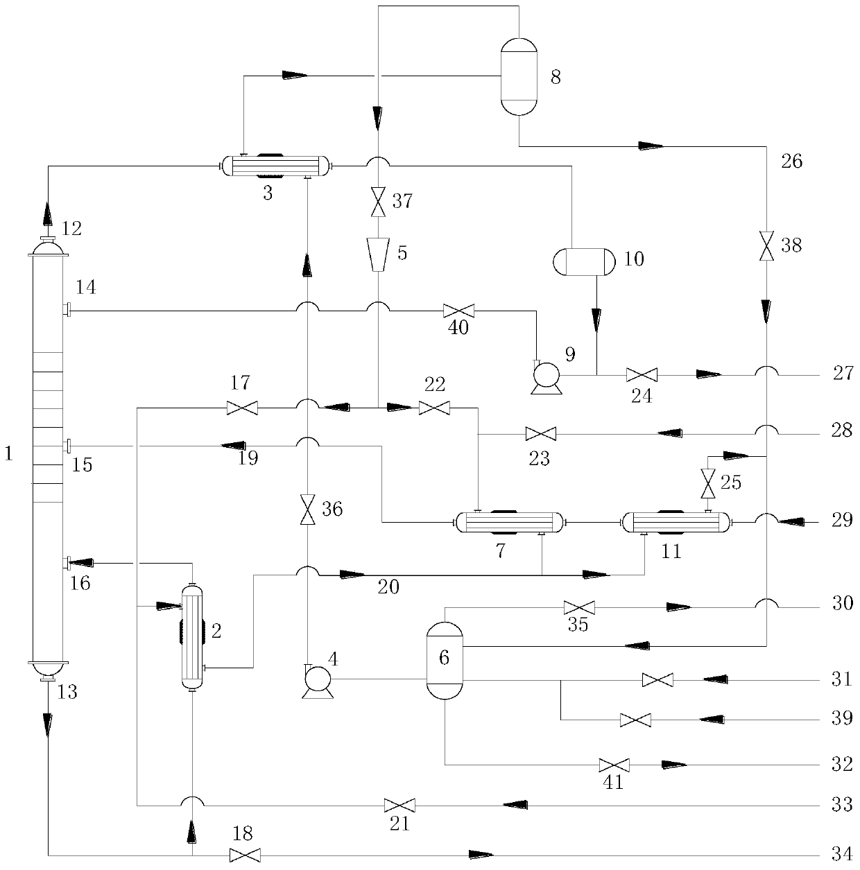
[0049] In the atmospheric rectification system where the raw material is 25°C and 90% by mass methanol aqueous solution, the vapor phase distilled from the top of rectification tower 1 is methanol vapor at 66.9°C and 99% by mass, and the bottom of the tower is 90.6°C with 90% by mass 8.3% methanol solution; open the H valve 35, by adjusting the vacuum system, ensure that the pressure in the water storage tank 6 is 26.2kPa, adjust the reasonable water consumption to make the water in the water storage tank 6 pass through the circulating water pump 4 and the I valve 36 Enter the shell-side inlet on the right side of the bottom of the condensing and vaporizing heat exchanger 3, and methanol vapor distilled from the gas phase outlet 12 at the top of the distillation column 1 at 66.9°C and with a mass percentage of 99% enters the tube side at the left end of the condensing and vaporizing heat exchanger 3 Inlet, the water and the 66.9°C, 99% by mass methanol vapor distilled from the ...

Embodiment 2

[0053]In the atmospheric rectification system where the raw material is 25°C and 90% by mass methanol aqueous solution, the vapor phase distilled from the top of rectification tower 1 is methanol vapor at 66.9°C and 99% by mass, and the bottom of the tower is 81°C with 90% by mass 49.5% methanol solution, open the H valve 35, by adjusting the vacuum system, ensure that the pressure in the water storage tank 6 is 26.2kPa, adjust the reasonable water consumption to make the water in the water storage tank 6 pass through the circulating water pump 4 and the I valve 36 Enter the shell-side inlet on the right side of the bottom of the condensing and vaporizing heat exchanger 3, and methanol vapor distilled from the gas phase outlet 12 at the top of the distillation column 1 at 66.9°C and with a mass percentage of 99% enters the tube side at the left end of the condensing and vaporizing heat exchanger 3 Inlet, the water and the 66.9°C, 99% by mass methanol vapor distilled from the to...

Embodiment 3

[0057] In the normal-pressure rectification system where the raw material is 25°C and 90% mass percent ethanol aqueous solution, the gas phase fraction distilled from the top of rectification tower 1 is 80.2°C and 95% mass percent ethanol water vapor, and the bottom of the tower is 86°C, mass percent Percentage of 50.3% ethanol solution, open the H valve 35, by adjusting the vacuum system, ensure that the pressure in the water storage tank 6 is 47.4kPa, adjust the reasonable water consumption, make the water in the water storage tank 6 pass through the circulating water pump 4 and I The valve 36 enters the shell-side inlet on the right side of the bottom of the condensing and vaporizing heat exchanger 3, and the 80.2°C and 95% by mass ethanol water vapor distilled from the gas phase outlet 12 at the top of the rectifying tower 1 enters the condensing and vaporizing heat exchanger 3 At the inlet of the tube at the left end, the water exchanges heat with the 80.2°C, 95% by mass e...


PUM


Abstract

The invention belongs to the fields of rectification and energy conservation and relates to a rectifying system and a rectifying method utilizing tower top gas-phase fraction condensation heat. In the rectifying system, water in a water storage tank and a gas-phase fraction distilled from the top of a rectifying tower perform heat exchange in a condensation and vaporization heat exchanger, water is vaporized into water vapor by the condensation and vaporization heat exchanger, the temperature of the water vapor is increased by a vapor compressor, high-grade water vapor with high temperature is obtained, and the high-grade water vapor can serve as a heating heat source of a reboiler or a raw material preheater, so that the potential heat of the tower top gas-phase fraction is utilized. According to the system and the method, consumption of externally supplied water vapor in the operating process of the rectifying tower is reduced, cooling water for condensation of the tower top gas-phase fraction is omitted, and the aims of saving energy and reducing consumption are fulfilled.

Description

technical field [0001] The technical field of rectification and energy saving of the present invention relates to a system and a method for rectifying heat by condensing gas phase fractions at the top of a tower. Background technique [0002] Due to its excellent separation ability, rectification operation is widely used in various fields of life and production. It is an important unit operation in the separation process. However, the rectification process consumes a lot of energy, and the energy utilization rate is not high. According to statistics, traditional The total energy consumed by the rectification operation accounts for about half of the total energy consumption of industrial production, which is a key step that restricts the entire production process; for example, although the production process of propylene oxide technology by HPPO method is simple, the product yield is high, and it is in line with green Clean production requirements, but the production process ...

Claims


Application Information

Patent Timeline
Patent Type & Authority Patents(China)
IPC IPC(8): B01D3/14B01D3/32
CPCB01D3/14B01D3/32
Inventor 刘常青宛捍东赵途张玉新胡永琪
Owner 河北美邦工程科技股份有限公司
Why Eureka
Try Eureka