Spray drying gun head assembly

A component and drying technology, which is applied in the directions of spray evaporation, spray device, spray device, etc., can solve the problems of easy generation of linear flow, insufficient atomization, and easy to exceed the moisture content, so as to improve the stability and improve the atomization effect. , The effect of preventing the reverse flow of gas into the liquid channel

Pending Publication Date: 2017-05-31
SHENZHEN SUNEVAP TECH
View PDF8 Cites 4 Cited by
  • Summary
  • Abstract
  • Description
  • Claims
  • Application Information

AI Technical Summary

Problems solved by technology

Due to the influence of factors such as high salt content and high viscosity of the material in the actual use of the existing spray drying gun, the nozzle is prone to be blocked by high temperature coking and the droplet is relatively large (generally, the diameter of the droplet is between 20 ~ 80um), at the same time, the existing atomization is insufficient, and it is easy to produce linear flow and other phenomena; at the same time, the existing spray drying gun is easy to exceed the standard due to the moisture content, and the heat exchange between the atomized material liquid and the hot air is not sufficient.
More importantly, when the liquid and gas are mixed, due to the change of the internal pressure of the atomization drying tower, the gas may be reversed to enter the liquid delivery channel, and this gas backflow phenomenon will lead to the reduction of the spray drying effect

Method used


Image

  • Spray drying gun head assembly
  • Spray drying gun head assembly
  • Spray drying gun head assembly

Examples


Embodiment Construction

[0021] The present invention will be described in detail below in conjunction with the implementations shown in the drawings, but it should be noted that these implementations are not limitations of the present invention, and those of ordinary skill in the art based on the functions, methods, or structural changes made by these implementations Equivalent transformations or substitutions all fall within the protection scope of the present invention.

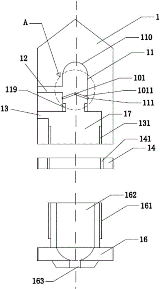
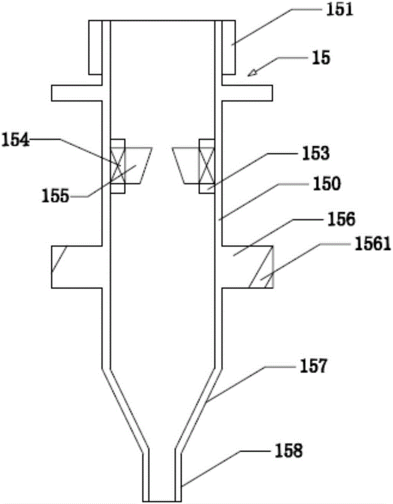
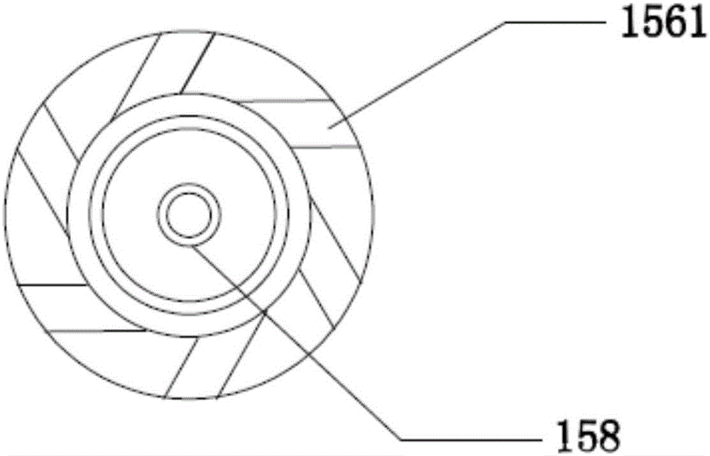
[0022] Please refer to Figure 1 to Figure 4 A specific embodiment of a spray drying gun tip assembly of the present invention is shown. The spray drying gun head assembly is installed inside the spray drying tower, and specifically includes: an axially screwed nozzle fixing head 1, an adjustment ring 14, an adjustment cover 16, and the inside of the adjustment cover 16 forms a cylindrical cavity 162, and The nozzle 15 accommodated by the nozzle fixing head 1 and the adjustment cover 16 together. The nozzle 15 includes a cylinde...


PUM


Abstract

The invention provides a spray drying gun head assembly which comprises a spraying nozzle fixing head, an adjusting ring, an adjusting cover and a spraying nozzle. The spraying nozzle comprises a barrel and a convex extending ring, the convex extending ring is provided with a plurality of rotational flow channels, a through hole is formed in the bottom of the adjusting cover, and a liquid inlet and an air inlet are formed in the side portion of the spraying nozzle fixing head; a first cavity and a second cavity which are through are formed inside the spraying nozzle fixing head, the liquid inlet is communicated with the first cavity, the air inlet is communicated with the second cavity, and a radial shrinkage part and a spraying pipe are formed in the tail end of the barrel; the spraying pipe penetrates the through hole, and an annular gap is formed between the spraying pipe and the through hole; and a reverse stopping device is arranged in the first cavity to prevent back flow of the liquid to the liquid inlet. In the spray drying gun head assembly, the reverse stopping device is arranged in a liquid conveying channel, and therefore the liquid and air mixing efficiency is improved, air can be effectively prevented from reversely flowing into the liquid channel, and the atomization effect is improved.

Description

technical field [0001] The invention relates to the field of spray drying equipment, in particular to a spray drying nozzle assembly. Background technique [0002] The spray drying equipment uses the pressure of the high-pressure pump to atomize the solution or slurry material into fine droplets, so that the surface area is significantly increased, and it can be quickly dried by sufficient heat exchange with hot air, so as to obtain powder or fine particle products. The spray drying gun is an important accessory in the spray drying equipment. [0003] A spray drying gun head must be assembled in the spray drying gun to atomize the liquid material. Due to the influence of factors such as high salt content and high viscosity of the material in the actual use of the existing spray drying gun, the nozzle is prone to be blocked by high temperature coking and the droplet is relatively large (generally, the diameter of the droplet is between 20 ~ 80um), at the same time, the exis...

Claims


Application Information

Patent Timeline
Patent Type & Authority Applications(China)
IPC IPC(8): B05B7/04B05B1/34B01D1/20B01D1/18
CPCB01D1/18B01D1/20B05B1/34B05B7/0433
Inventor 郭亮周齐鲍燕娟张小江
Owner SHENZHEN SUNEVAP TECH
Why Eureka
Try Eureka