
Misaligned rectifying and dragging device of plate rolling machine

A plate rolling machine and wrong side technology, applied in the field of wrong side deviation correction, can solve the problems of increasing the workload of deviation correction, the difficulty of rounding, the existence of safety hazards, and poor cylinder forming, so as to shorten the time of deviation correction, avoid the deformation of the lower ra Improvement effect of ellipse phenomenon

Inactive Publication Date: 2017-05-31
SHANGHAI ZHENHUA HEAVY IND
View PDF4 Cites 4 Cited by
  • Summary
  • Abstract
  • Description
  • Claims
  • Application Information

AI Technical Summary

Problems solved by technology

The existing plate rolling machine uses a plate clamp or a plate structure to pull the plate upwards during the rolling process through a crane, and hangs the end of the plate to prevent the deformation of the cylinder due to its own weight, but the effect is unsatisfactory. It is still poor, and the closed Yuantong is still in the shape of an ellipse, even distorted
Moreover, the risk of driving is relatively high during use, and there are potential safety hazards
If the pipe fittings have large radial and longitudinal deviations in the process of sheet metal rolling, it will increase the workload of post-deviation correction and the difficulty of rounding after longitudinal seam welding

Method used


Image

  • Misaligned rectifying and dragging device of plate rolling machine
  • Misaligned rectifying and dragging device of plate rolling machine
  • Misaligned rectifying and dragging device of plate rolling machine

Examples


Embodiment Construction

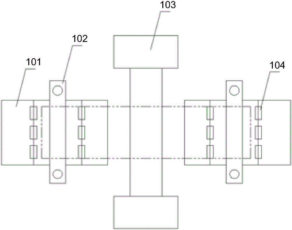
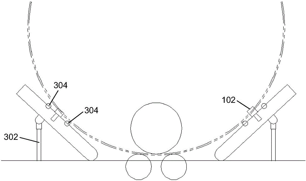
[0017] refer to figure 1 as shown, figure 1 Disclosed is a structural diagram of a misalignment correcting and dragging device of a plate bending machine according to an embodiment of the present invention. The misalignment correcting and dragging device of the plate bending machine includes: a dragging chassis 101 , a longitudinal deviation correcting mechanism 102 and a radial deviation correcting mechanism 104 . The longitudinal deviation correction mechanism 102 is installed on the dragging chassis 101, and the longitudinal deviation correction mechanism 102 performs longitudinal deviation correction on the plate being rolled. The radial deviation correction mechanism 104 is installed on the dragging chassis 101, and the radial deviation correction mechanism 104 performs radial deviation correction on the plate being rolled. The misalignment correction and dragging devices of the plate bending machine are arranged in pairs, and the misalignment correction and dragging de...


PUM


Abstract

The invention discloses a misaligned rectifying and dragging device of a plate rolling machine. The misaligned rectifying and dragging device comprises a dragging base plate, a longitudinal rectifying mechanism and a radial rectifying mechanism, wherein the longitudinal rectifying mechanism is arranged on the dragging base plate for carrying out longitudinal rectifying on a plate which is being rolled; the radial rectifying mechanism is arranged on the dragging base plate for carrying out radial rectifying on the plate which is being rolled; the longitudinal rectifying mechanism comprises a beam, a clamping rod and a drive mechanism; the beam is arranged on the dragging base plate and is provided with a lateral groove; the clamping rod is arranged on the beam, and the clamping rod is arranged in the lateral groove and can laterally move along the groove; the drive mechanism is arranged on the beam and drives the clamping rod to laterally move along the groove; the clamping rod is in contact with the plate which is being rolled, and the plate is driven to laterally move to carry out longitudinal rectifying on the plate; the radial rectifying mechanism comprises a jacking mechanism and support rollers; the jacking mechanism is connected with the dragging base plate and adjusts the inclination angle of the dragging base plate; and the support rollers are arranged on the dragging base plate to support the plate which is being rolled.

Description

technical field [0001] The invention relates to the technical field of steel material processing, and more specifically, relates to a technology for correcting wrong edges in the process of plate material processing. Background technique [0002] Pipe fittings are important components in steel structures. With the rapid development of the wind power market, the demand for wind power pipe piles has increased significantly. The pipe fittings of the steel structure are all obtained by the process of rolling the steel plate. The plate rolling machine is the equipment for the steel plate rolling process. The structure of the currently used plate rolling machines is relatively simple. Although the cost is disclosed, the degree of automation and processing accuracy are relatively low. [0003] The main problem encountered by existing plate rolling machines during the steel plate rolling process is that it is difficult to control the radial deviation and longitudinal deviation of ...

Claims


Application Information

Patent Timeline
Patent Type & Authority Applications(China)
IPC IPC(8): B21D5/14B21D43/09
CPCB21D5/14B21D43/09
Inventor 戴伟邹纪祥孙会见何继弘汪成
Owner SHANGHAI ZHENHUA HEAVY IND
Learn More