

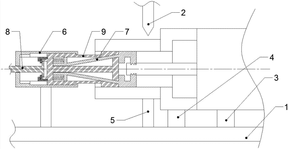
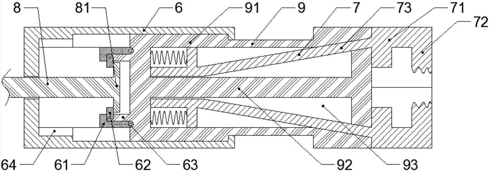
Riveting device for lamp tube electrodes
A technology of lamp tube and punching riveting, which is applied in the direction of feeding device, positioning device, storage device, etc. It can solve the problems that affect the stability of product quality, small diameter of copper electrode through hole, and low manual production efficiency, so as to reduce the bending of wires Probability, reduce workload, reduce the effect of work intensity
- Summary
- Abstract
- Description
- Claims
- Application Information
AI Technical Summary
Problems solved by technology
Method used
Image

Examples
Embodiment Construction
[0015] Embodiments of the technical solutions of the present invention will be described in detail below in conjunction with the accompanying drawings. The following examples are only used to illustrate the technical solutions of the present invention more clearly, and therefore are only examples, rather than limiting the protection scope of the present invention.
[0016] It should be noted that, unless otherwise specified, the technical terms or scientific terms used in this application shall have the usual meanings understood by those skilled in the art to which the present invention belongs.
[0017] In the description of the present application, it is to be understood that the terms "height", "vertical", "horizontal", "inner", "outer", "axial", "radial", "circumferential" etc. indicate The orientation or positional relationship is based on the attached figure 2 The orientations or positional relationships shown are only for the convenience of describing the present inve...
PUM
 Abstract
Description
Claims
Application Information